Rainy day today, got the prototype firmware working. For whatever reason using a display and sending pulses to a stepper motor with the Uno was a real struggle. I tried several different libraries for the I2C LCD and stepper motor and wasn’t able to get a single update done quickly enough to fit between steps. This was easy to hear, sometimes you can see it, and depending on the pulse frequency it would even stall the stepper or cause it to reverse direction if it was changing speed at the same time. At this point I am just not updating the display in the “Jog” mode until you stop or change direction – the numbers are really meaningless anyways and if you’re cutting you should adjust it by looking at the tool not the screen. My 3D printer can do it without a problem, wonder how?
Month: May 2020
bookmark_borderIdea: Mini-Lathe “Smart” Power Feed
This idea has been floating around in my brain for awhile. I am finally getting started on it, and hopefully writing it down here will help me remember to finish it.
The “problem”
The mini lathe uses change gears for the leadscrew; for anything other than threading they are a pain in the butt (in my opinion). Changing the feed rate is annoying, and for regular turning I think it would be great if it were variable, just like a power feed on a milling machine.
This isn’t a novel idea, but I won’t let that stop me. Here are some others who have done this already:
- http://www.mini-lathe.com/Mini_mill/Modifications/Power_feed/power_feed.htm
- https://www.homemadetools.net/forum/mini-lathe-carriage-feed-70736
- http://www.varmintal.com/alath.htm#Ultra_Fine
I’m aiming for overkill, so here’s what I’m going to try to make this do:
- Use a stepper or DC motor coupled to the tailstock end of the leadscrew. Ideally permanently attached and can coast if you are using the change gears, or with some kind of clutch otherwise
- Microcontroller and rotary encoder for closed loop (if we use a DC motor) speed and position control. Knob to set the speed.
- Several “modes”
- Jog: feed in either direction at the set speed, like a normal power feed
- Set: after jogging to a position, save that position to memory for later
- Auto: feed in selected direction up to the saved position.
- LCD to display the current speed, saved speed and saved positions
“Auto” mode (might rename that) is the neat part. I want to save two feed rates, one for cutting and another for reversing back to the beginning of the cut. With the half nuts engaged the whole time, first you would enter “set” mode, jog to the end of your cut and zero this “left” position. Then jog back past the start of your cut and zero this “right” position. A feed rate for each direction can also be saved. Now return to “Auto” mode. Setting the switch to move left will feed in at the cutting speed you set and will stop when it reaches that position. Retract your tool, then jog right and it will move back to the start of your cut at a much higher feed rate, stopping at the right position. I think this will be neat for taking repeated cuts and getting the feed rate just right every time. Another way to say all that is “I want a power feed with virtual stops and fast reverse”.
Using a rotary encoder or stepper on the leadscrew means that the positions are always relative and will be lost if you disengage the half nuts. Backlash will still exist, but if you approach your set points from the right direction I don’t think it will be a problem. On the upside, since we’re not measuring real units, (just pulses and steps) there should be no calibration required and it should be easy to use a variety of encoders and steppers regardless of their resolution. We can display numbers on the LCD for position and speed but we don’t have to care if they are inches, rotations, minutes, whatever. If this works out I’ll probably add it to my larger lathe as well.
I tried to measure the torque required by fixing a rod perpendicular to the leadscrew, hanging a weight on it, and measuring the radius where it started to move (I’ll add a photo of how I did this if I can find one). This was all done with the half nuts engaged
- .40 Nm to overcome friction only
- .93 Nm to do a very light cut
- 1.16 Nm is my guess for a minimum
It’s probably best to double that or more – the required force will increase depending on the cut you’re taking and how much friction there is between all the moving parts. There is probably a big difference between dirty and lubricated ways. I ordered what was advertised as a 1.9 Nm NEMA 23 stepper, and I’m going to use a timing belt with 20 and 60 tooth pulleys, so that should reduce the maximum speed and triple that torque number. My guess at speed was that 0-200 RPM would be appropriate, and it may be possible to get away with a smaller motor and larger reduction.
I’ve got some parts on order and I’ll work on the electronics while I wait. If this works out I’ll try to document it so that it’s reproduceable. It’s going to be a challenge to condense all these switches and buttons into a small package that doesn’t look humongous compared to a mini-lathe!
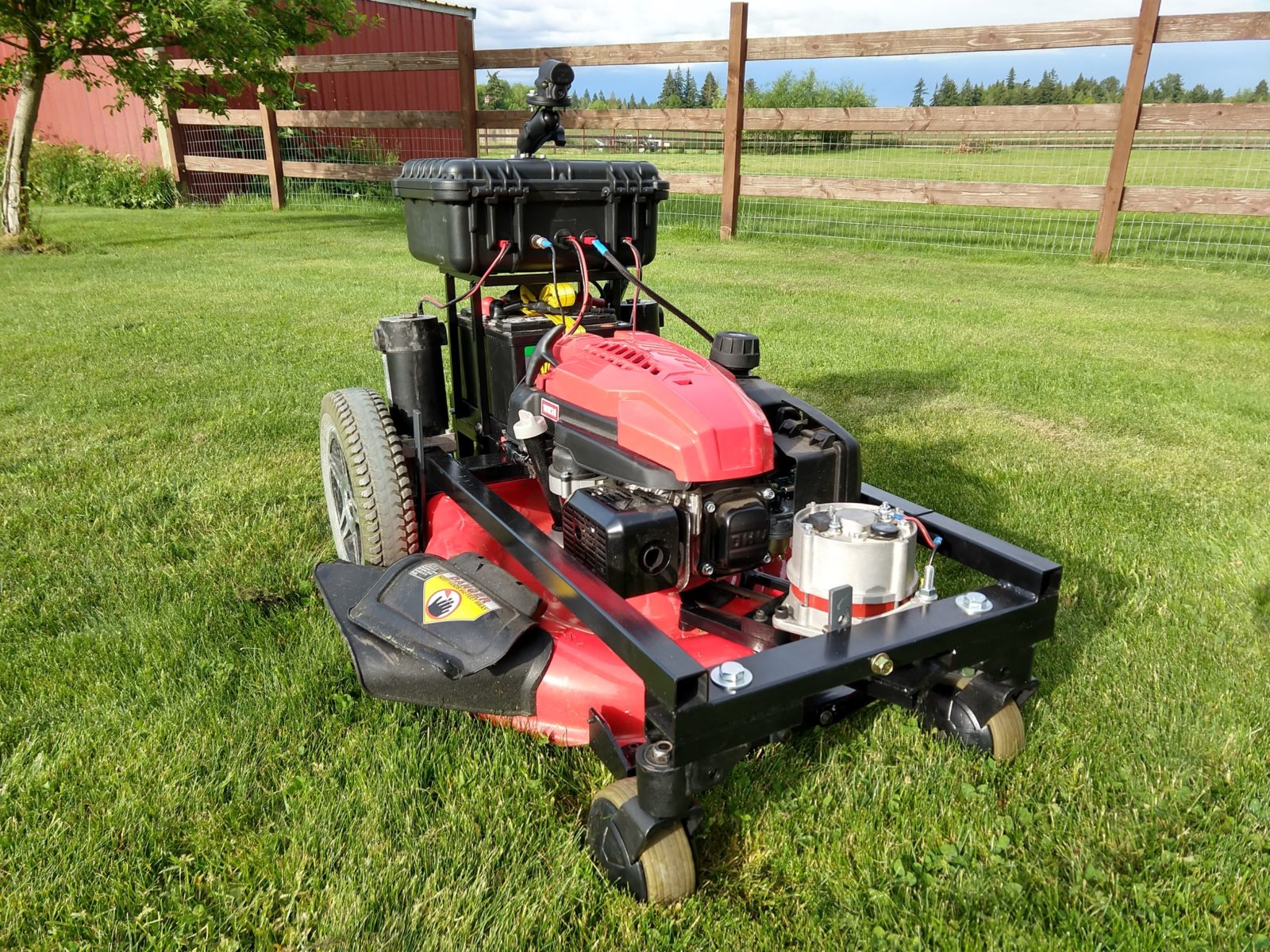
bookmark_borderRemote Control Lawnmower
Just wrapped this up and delivered to it’s new owner. It has just about everything except for autopilot! I’ll post some followups with the details, for now here are the specs:
- Craftsman M270 21″ mower
- 24v wheelchair motors and batteries
- 24v alternator (never run out of juice, only run out of gas!)
- Electric start – remote controlled of course
- Dimension Engineering Sabertooth 2×32 motor controller
- FPV camera for mowing at a distance
This is also posted on instructables here: https://www.instructables.com/id/Remote-Control-Lawn-Mower/
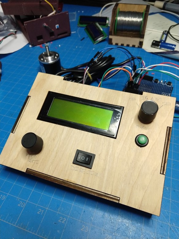
bookmark_borderVacuum Former Done!
New circuit board arrived, firmware written, all wiring complete, and it’s working! I posted some info in an instructable here: https://www.instructables.com/id/Revive-a-Vacuum-Former/
The rest of this post is for future-me if I need to troubleshoot my work and can’t find it on my hard drive:
//Replacement controller for Clarke Vacuum Former 1820
//Elliotmade 4/27/2020
//Manual for the machine: https://www.abbeon.com/ItemFiles/Manual/1820.pdf

/*
 * Components attached to the arduino:
 * 4 heater relays (12v, using an IRFZ44 n-channel mosfet to switch these
 * 1 buzzer relay
 * 4 heater potentiometers
 * 2 7-segment displays each using a TM1637 driver
 * 1 Rotary encoder with button
 * 2 existing switches from the machine for the heater location
 *
 * Operation should be similar to this:
 * Power on the machine, switch heaters on and off slowly according to power level set on the knobs
 * Timer set value is stored in eeprom, displayed on the first 7-segment display
 * Changing the timer set value is done with the rotary encoder
 * Extending the heater triggers a switch and the timer should count down on the second display
 * When the timer reaches zero the buzzer should be turned on
 * Retracting the heater triggers a switch and the timer should be reset and buzzer turned off
 *
 * Pay attention to the heater position switches and which order they get pushed in
 * States for the timer:
 *  Not running, buzzer not triggered (normal idle status, assume we started from here)
 *  Running, buzzer not triggered (heater extended)
 *  Running, buzzer triggered (heater extended, but time has run out)
 *  Not running, buzzer not triggered (heater retracted, timer is reset and buzzer is canceled)
 */

//////////////////////////////////////////////libraries////////////////////////////////////////////////////////////
#include <RotaryEncoder.h>
//http://www.mathertel.de/Arduino/RotaryEncoderLibrary.aspx
//https://github.com/mathertel/RotaryEncoder

#include "OneButton.h"
//https://github.com/mathertel/OneButton

#include <SimpleTimer.h>
//https://github.com/jfturcot/SimpleTimer

#include <TM1637Display.h>
//https://github.com/avishorp/TM1637

#include <EEPROMex.h>
//https://github.com/thijse/Arduino-EEPROMEx

//////////////////////////////////////////Pins////////////////////////////////////////////////////////////////
const int encoderButton = A1;
const int encoderA = A2;
const int encoderB = A3;
const int timerStart = 7; //D7
const int timerReset = 6; //D6
const int buzzer = 8; //D8
const int dispClock1 = 2; //D2
const int dispClock2 = 4; //D4
const int dispData1 = 3; //D3
const int dispData2 = 5; //D5
const int heatRelay[4] = {12,11,10,9}; //D9-D12
const int heatKnob[4] = {A4,A5,A6,A7};


///////////////////////////////////////////Constants///////////////////////////////////////////////////////////////
//This will impact the duration of the on/off cycles for the heaters.  Milliseconds.  Heaters should stay on for the duty cycle percent, then off for 100-duty cycle
const unsigned long heatIntervalMult = 1000;

//read heater knobs and update heaters every (milliseconds)
const int updateHeatInterval = 500;

//minimum duty cycle for heaters (old controls were approx. 55% according to the manual "power reduction is 45% on setting 1"
const int minDutyPct = 55;

//thresholds for knob to identify zero and max heat (0-1023)
const int minThreshold = 30;
const int maxThreshold = 1000;

const byte heaterCount = 4;

//eeprom memory locations
const int minAddress = 10;
const int secAddress = 20;
const int memBase = 350;

////////////////////////////////////////////Variables//////////////////////////////////////////////////////////////

bool heatStatus[4] = {false,false,false,false};   //current on/off status of a heater
int heatSetting[4] = {0,0,0,0};                   //current heat setting 0-100 percent, updated when the knobs are read
unsigned long heatLastChange[4] = {0,0,0,0};      //last time in milliseconds that the heater was turned on
bool timerRunning = false;                        //state of the timer
bool buzzerOn = false;                            //state of the buzzer
bool minutesMode = false;                         //change behavior of encoder based on this
int minutes;                                      //timer set time
int seconds;                                      //timer set time
int elapsedMinutes = 0;                           //timer current countdown time
int elapsedSeconds = 0;                           //timer current countdown time
bool rollover = false;                            //used to help display the countdown

//Initialize some things
SimpleTimer countdownTimer;
RotaryEncoder encoder(encoderA, encoderB);
OneButton startSwitch(timerStart, true);
OneButton resetSwitch(timerReset, true);
OneButton encoderButt(encoderButton, true);
TM1637Display display1(dispClock1, dispData1);
TM1637Display display2(dispClock2, dispData2);


void setup() { ////////////////////////////////////////Setup///////////////////////////////////////////////////
//Serial for debugging
Serial.begin(9600);

Serial.println("Setup Start");

//interrupts for encoder
PCICR |= (1 << PCIE1);    // This enables Pin Change Interrupt 1 that covers the Analog input pins or Port C.
PCMSK1 |= (1 << PCINT10) | (1 << PCINT11);  // This enables the interrupt for pin 2 and 3 of Port C.

// Set Up EEPROM
EEPROM.setMemPool(memBase, EEPROMSizeNano);

//pins
pinMode(buzzer, OUTPUT);
for (byte i = 0; i <= heaterCount - 1; i++) {
  pinMode(heatRelay[i], OUTPUT);
  pinMode(heatKnob[i], INPUT);
}

//button functions
startSwitch.attachClick(startTime);
resetSwitch.attachClick(resetTime);
encoderButt.attachClick(encoderClick);
encoderButt.attachLongPressStart(saveTime);

//Load the stored timer value
minutes = EEPROM.readInt(minAddress);
seconds = EEPROM.readInt(secAddress);


//displays
display1.setBrightness(2);
display2.setBrightness(2);
display1.showNumberDec(8008);
display2.showNumberDecEx(8008,0x40,true);
delay(50);

updateDisplay1();

countdownTimer.setInterval(1000,incrimentTimer); //make timer count every second
countdownTimer.setInterval(updateHeatInterval,readKnobs);
countdownTimer.setInterval(250,updateHeatStatus);
countdownTimer.setInterval(250,updateHeatRelays);

Serial.println("Setup Complete");
} //////////////////////////////////////////////End Setup/////////////////////////////////////////////////////


void loop() { ////////////////////////////////////Loop/////////////////////////////////////////////////////
  //monitor buttons
  startSwitch.tick();
  resetSwitch.tick();
  encoderButt.tick();
  readEncoder();
  countdownTimer.run();
  checkTimer();
  updateDisplay1();
  updateDisplay2();
  updateBuzzer();
} //////////////////////////////////////////////End Loop/////////////////////////////////////////////////////


void encoderClick() { //When the encoder button is clicked, change from minutes to seconds for timer adjustment

  minutesMode = !minutesMode; //toggle time setting modes
  Serial.print("Mode: ");
  Serial.println(minutesMode);
}

void readEncoder() {
      static int pos = 0;
      int newPos = encoder.getPosition();


      if (!timerRunning) { //only let the set time be changed when the timer is not counting down
        if (pos != newPos) {


          if (minutesMode) {
          minutes = minutes + (newPos - pos);

          }
          else {
            seconds = seconds + (newPos - pos);
            if (seconds == 60) {
              seconds = 0;
              minutes++;
            }
            if (seconds < 0) {
              seconds = 59;
              minutes--;
            }
          }
          pos = newPos;

          minutes = constrain(minutes,0,59);
          seconds = constrain(seconds,0,59);

          Serial.print("Minutes: ");
          Serial.print(minutes);
          Serial.print(" Seconds: ");
          Serial.println(seconds);
        }
      }
      else {
        encoder.setPosition(pos); //reset the encoder, as if it didn't move while the timer was counting
      }
}

void startTime() { //When the heater is extended, start counting down
  if (!timerRunning) {
    timerRunning = true;
    elapsedSeconds = 0;
    elapsedMinutes = 0;
    Serial.println("Timer Started");
  }
}

void resetTime() { //When the heater is retracted, stop counting down, rest the timer, and shut off the buzzer
  if (timerRunning) {
    timerRunning = false;
    buzzerOn = false;
    elapsedMinutes = 0;
    elapsedSeconds = 0;
  }
  updateBuzzer();
}

void saveTime() { //When the encoder knob is held down, save the set time to EEPROM
  EEPROM.writeInt(minAddress, minutes);
  EEPROM.writeInt(secAddress, seconds);
  Serial.println("Timer setting saved to EEPROM");
}

void incrimentTimer() { //update the elapsed time variables after each second passes
  if (timerRunning) {
    elapsedSeconds++;
    if (elapsedSeconds == seconds && rollover == false) {  //used to help display differently if the original number of seconds have passed
        rollover = true;
        elapsedSeconds = 60;
        elapsedMinutes++;
    }
    if (elapsedSeconds == 60) {
      elapsedSeconds = 0;
      elapsedMinutes++;
    }
  }
}

void checkTimer() { //If the timer is running, sound the buzzer once it has reached zero
  if (elapsedMinutes >= minutes && (elapsedSeconds % 60) >= seconds && !buzzerOn) {
    Serial.println("Timer has reached zero");
    buzzerOn = true; //turn on the buzzer
    elapsedSeconds = 0; //reset the elapsed time so it can be displayed counting up easily
    elapsedMinutes = 0;
  }
}

void updateBuzzer() { //Turn buzzer on/off based on the variable
  if (buzzerOn) {
    digitalWrite(buzzer, LOW);
    //Serial.println("Buzzer On");
  }
  else {
    digitalWrite(buzzer, HIGH);
    //Serial.println("Buzzer Off");
  }
}

void updateDisplay1() {
  display1.showNumberDecEx(minutes * 100 + seconds, 0x40, true);  //Set time should always show on display 1
}

void updateDisplay2() {
  if (timerRunning) {
    if (buzzerOn) { //count up if the buzzer is on (timer has reached zero)
      display2.showNumberDecEx((elapsedMinutes) * 100 + (elapsedSeconds), 0x40, true); //count up.  These were reset to 0 when the timer ran out
    }
    else if (rollover == true) {  //count down from 60 seconds
      display2.showNumberDecEx((minutes - elapsedMinutes) * 100 + (60 - elapsedSeconds), 0x40, true); //count down
    }

    else { //count down from the original number of seconds
      display2.showNumberDecEx((minutes - elapsedMinutes) * 100 + (seconds - elapsedSeconds), 0x40, true); //count down
    }
  }
  else {
    display2.showNumberDecEx(minutes * 100 + seconds, 0x40, true); //show the same thing on 2 as 1
  }

}

void readKnobs() { //read knob position and update the heat setting array
  for (byte j = 0; j <= heaterCount - 1; j++) {

    if (analogRead(heatKnob[j]) < minThreshold) {
      heatSetting[j] = 0;
    }
    else if (analogRead(heatKnob[j]) > maxThreshold) {
      heatSetting[j] = 100;
    }
    else {
      heatSetting[j] = map(analogRead(heatKnob[j]),0,1023,minDutyPct * 10,maxThreshold)/10;
    }


  }
//Serial.println(" ");
}

void updateHeatStatus() { //update the on/off array for each heater based on the knob position
  //calculate the time to the next change
unsigned long curMillis = millis();

  for (byte m = 0; m <= heaterCount - 1; m++) {
    if (heatSetting == 0 && heatStatus[m] == true) {          //fully off if the knob is at the minimum position
      heatStatus[m] = false;
      heatLastChange[m] = curMillis;
    }
    else if (heatSetting == 100 && heatStatus[m] == false) {   //fully on if the knob is at the max position
      heatStatus[m] = true;
      heatLastChange[m] = curMillis;
    }

    else if (heatStatus[m] == true) {
      if (heatLastChange[m] + heatSetting[m] * heatIntervalMult < curMillis) {  //if the heater is currently on, wait until last change time + (duty cycle * multiplier) seconds have gone by then turn it off
        heatStatus[m] = false;
        heatLastChange[m] = curMillis;
      }
    }
    else {  //if the heater is currently off, wait until last change time + (100 - duty cycle * multiplier) seconds have gone by then turn it on
      if (heatLastChange[m] + (100 - heatSetting[m]) * heatIntervalMult < curMillis) {  //if the heater is currently off, wait until last change time + (100 - duty cycle) * multiplier seconds have gone by then turn it off
        heatStatus[m] = true;
        heatLastChange[m] = curMillis;
      }
    }


  }


}

void updateHeatRelays() { //Turn heaters relays on or off
  for (byte k = 0; k <= heaterCount - 1; k++) {

    if(heatStatus[k] == true) {
      digitalWrite(heatRelay[k], HIGH);
    }
    else {
      digitalWrite(heatRelay[k], LOW);
    }
}


}

ISR(PCINT1_vect) { // The Interrupt Service Routine for Pin Change Interrupt 1
  encoder.tick(); // just call tick() to check the state.
}bookmark_borderNew (old) Vacuum Forming Machine
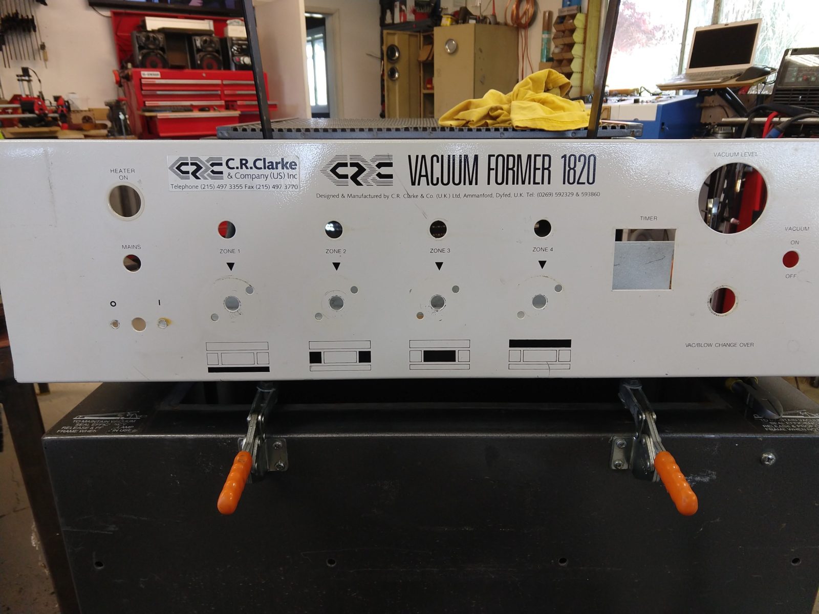
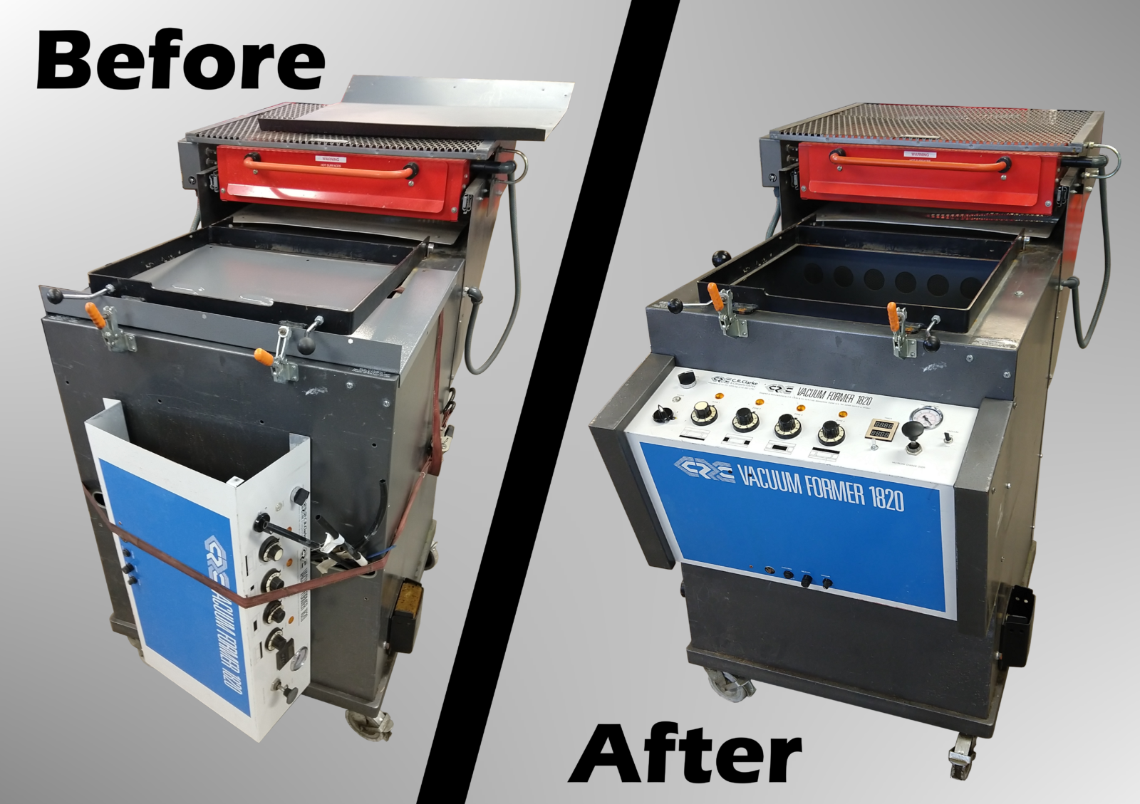
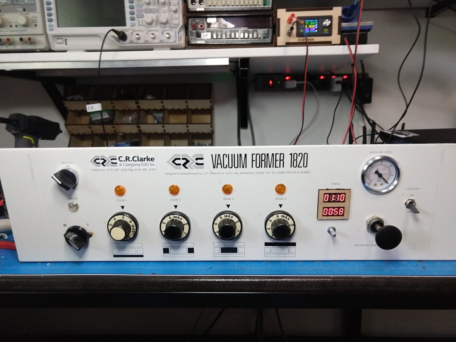
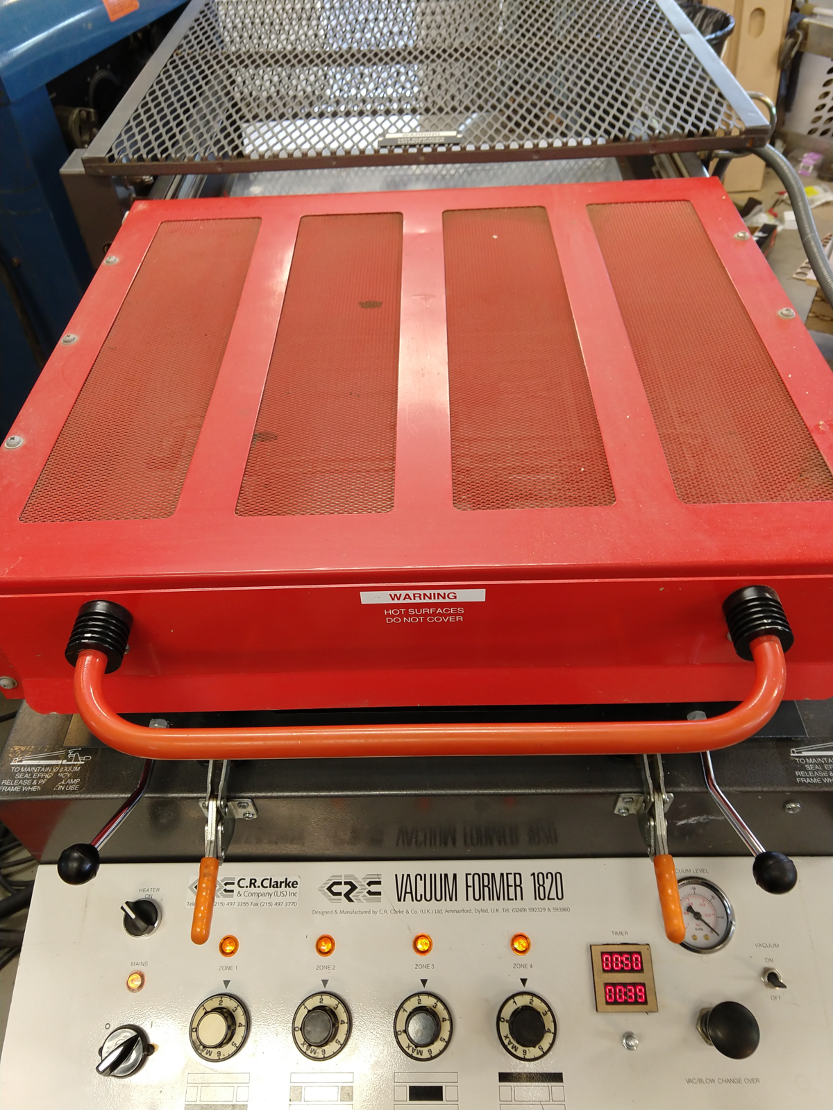
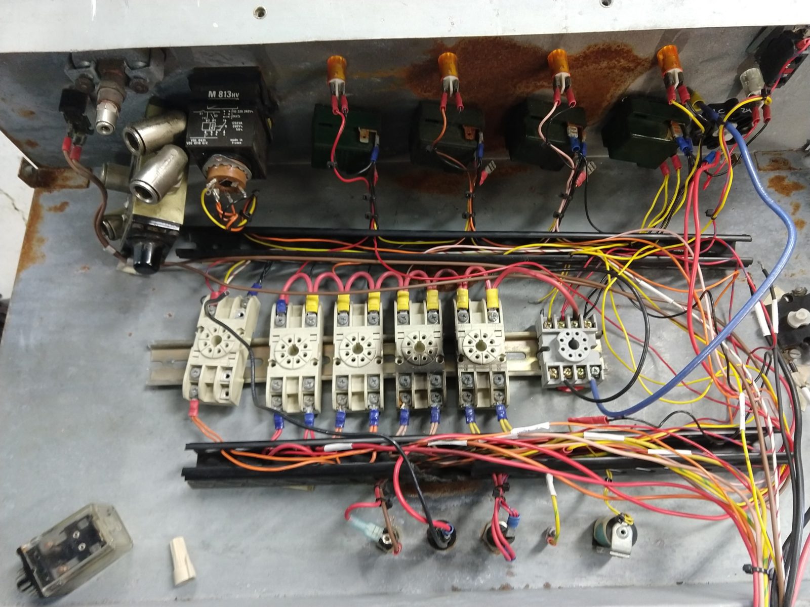
I just became the surprise owner of this vacuum forming machine:
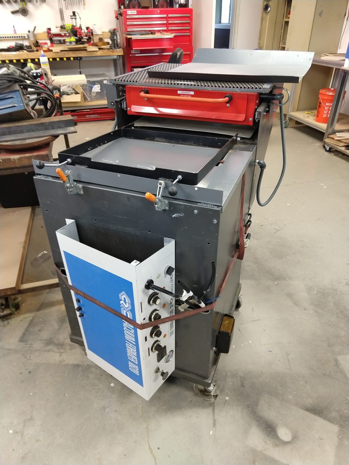
This is a C. R. Clarke Vacuum Former 1820. Looks like this model is still made currently (link to site), but I would guess that this one was made in the mid ’90s. The concept is fairly straightforward: a form/mold is placed on a moving platform inside, material is clamped in place over it, the heater slides forward to heat it, then the mold is raised and vacuum applied. This one has a few things wrong with it:
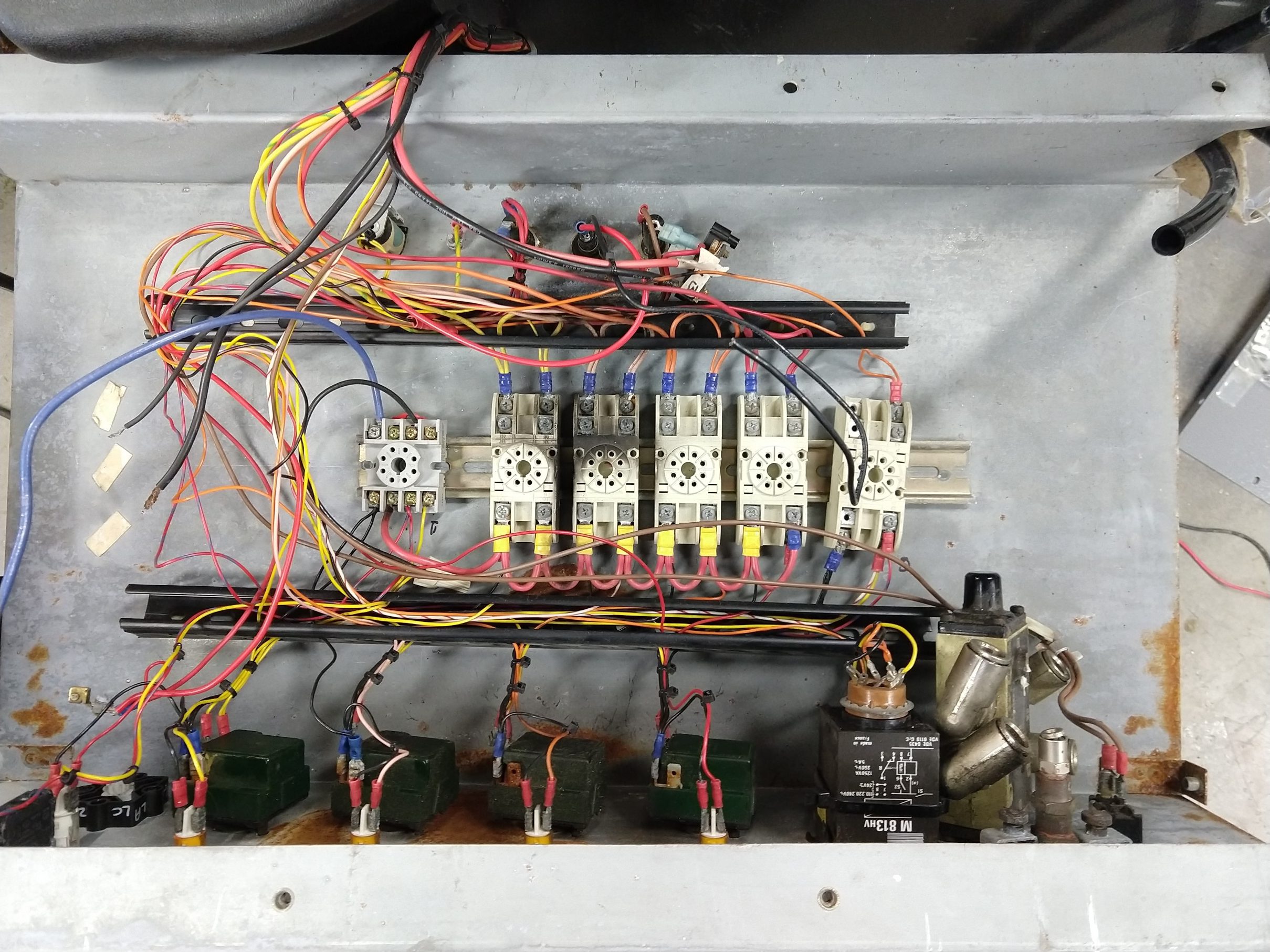
- Control panel has been partially removed
- Something electrical caught fire or let out some smoke
- Power switch broken/disassembled and there are many wires disconnected (and a suspicious wire nut, always a bad sign)
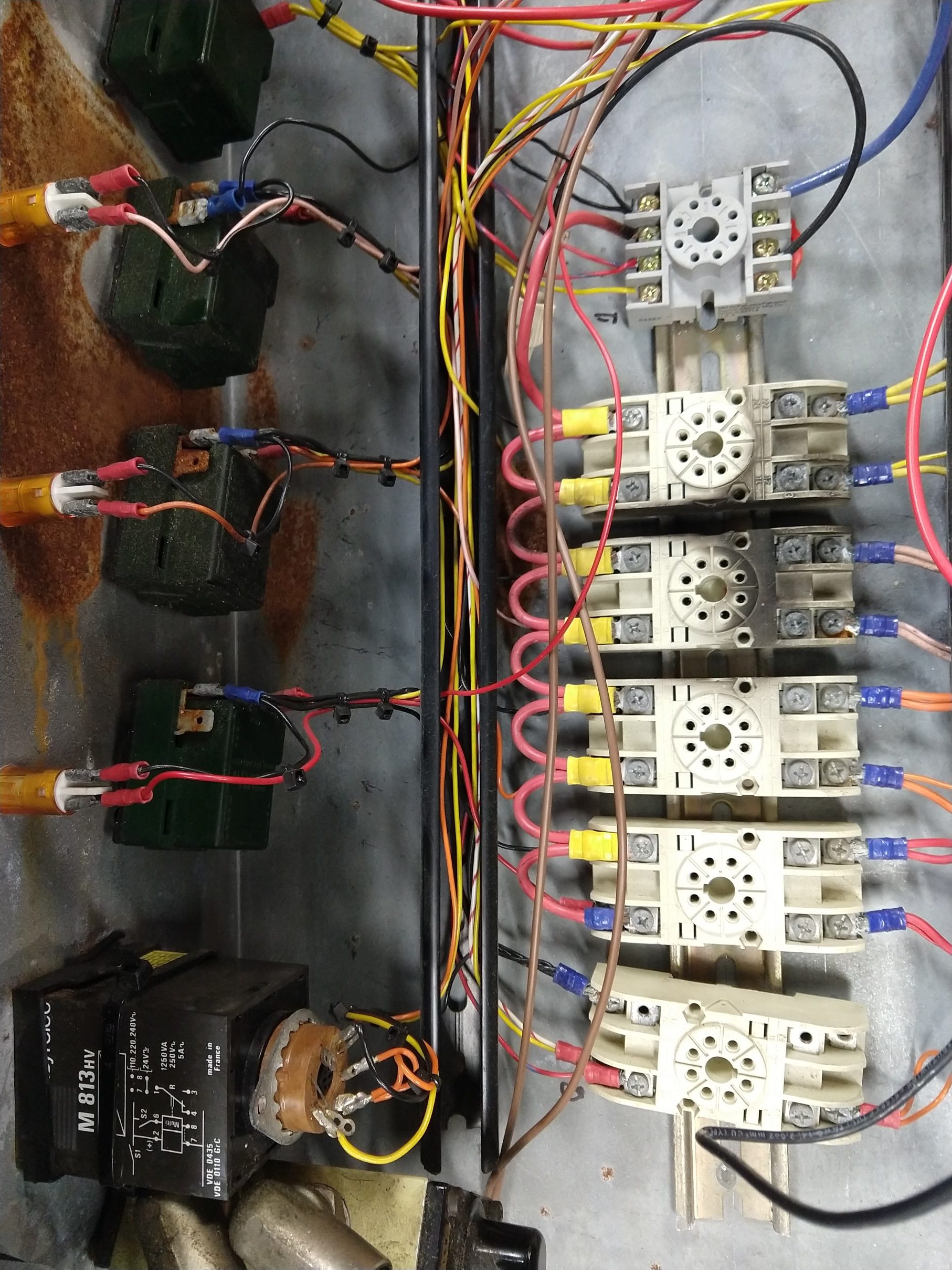
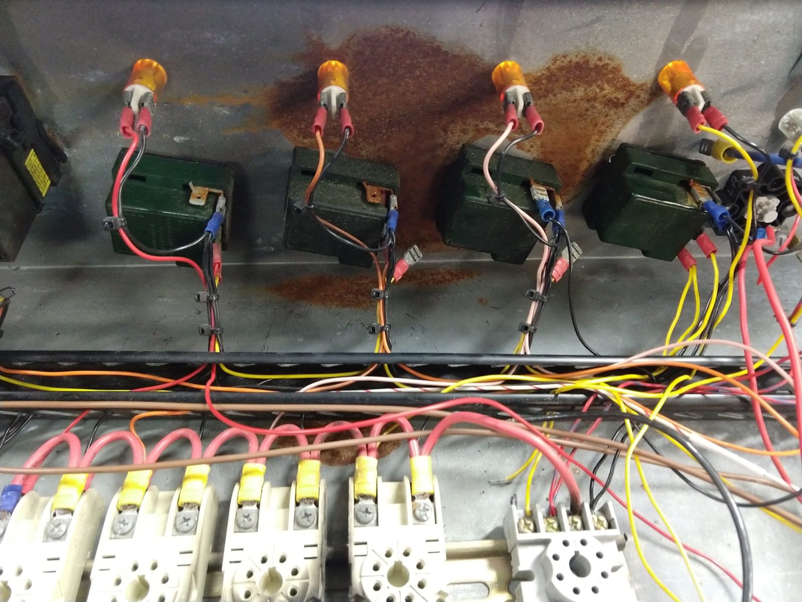
- One of the relay bases is broken from it’s rail, another relay is melted, and many of the relay contacts look worn
- One of the heat controllers is cracked open, all are rusted
- Corrosion on all of the connectors. It probably spent some time outside
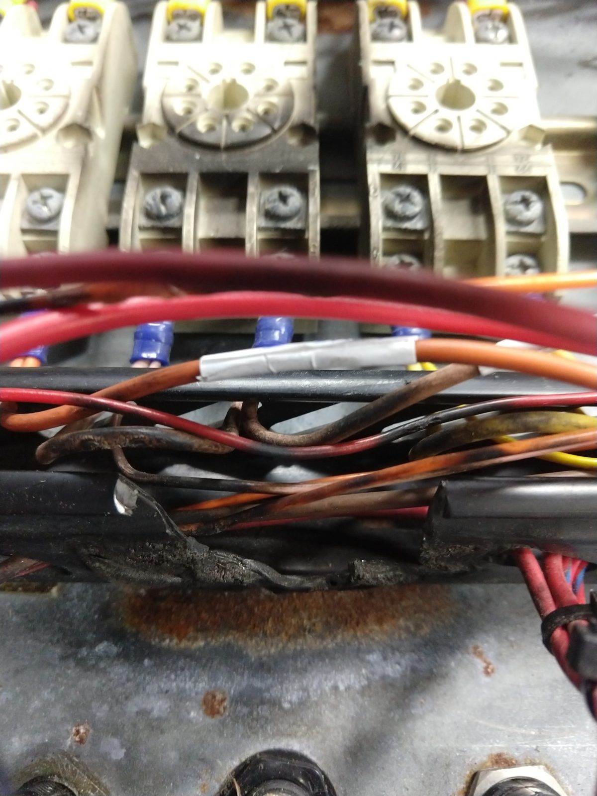
The controls are completely electromechanical except for the timer, which has exactly two transistors in it, and everything in the panel including the indicator lights runs at 220 volts. The heating elements and vacuum system look like they’re in good shape, so I would say it’s worth fixing. With that said… the amount of corrosion on everything in the panel and the obvious burn marks from a previous fire give me doubts about just hooking everything back up. Because of the high voltage, I would want to replace all of the heater controls, timer, connectors, and relays… and the original stuff isn’t super easy to come by. I plan to replace it all, but first I have to understand how it was supposed to work.
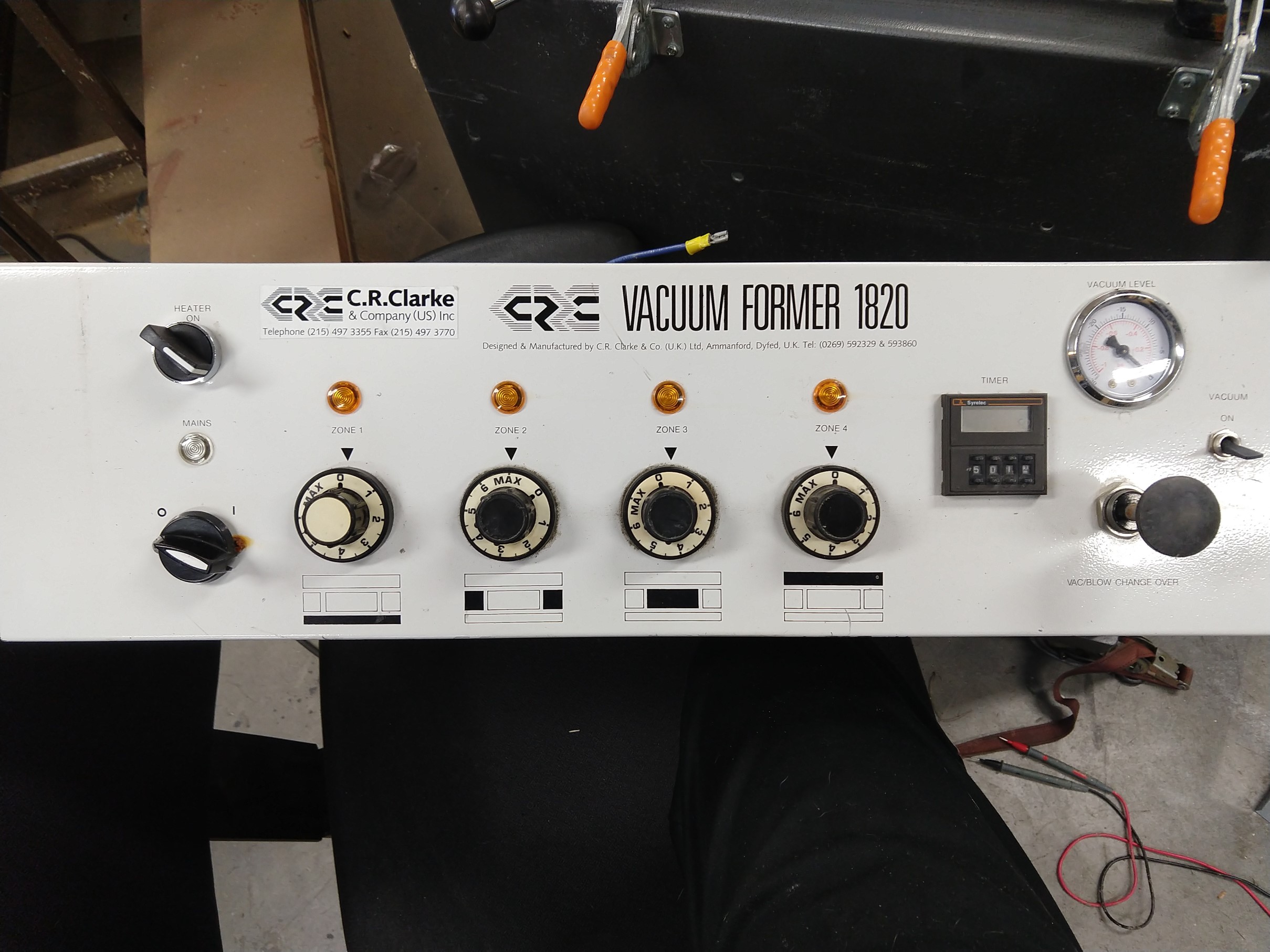
Ignoring the vacuum part, there are only a couple things that actually have to happen: the heat level needs to be regulated, and a timer needs to tell the operator how long to keep the heat over the material. Heat regulation appears to be open loop with a sort of thermostat – Diamond H 30ER1HT 38. From what I gather these are also referred to as a “simmerstat” and are used on some kinds of hot plates/kitchen/catering type appliances. Instead of sensing the temperature of air like a thermostat, there is an internal heater acting on the bimetallic strip that opens and closes the contacts. When the knob is off the contacts are open, when it is at MAX they are closed, and in between it cycles open and closed. Basically this is PWM with variable duty cycle, but with a very slow frequency.
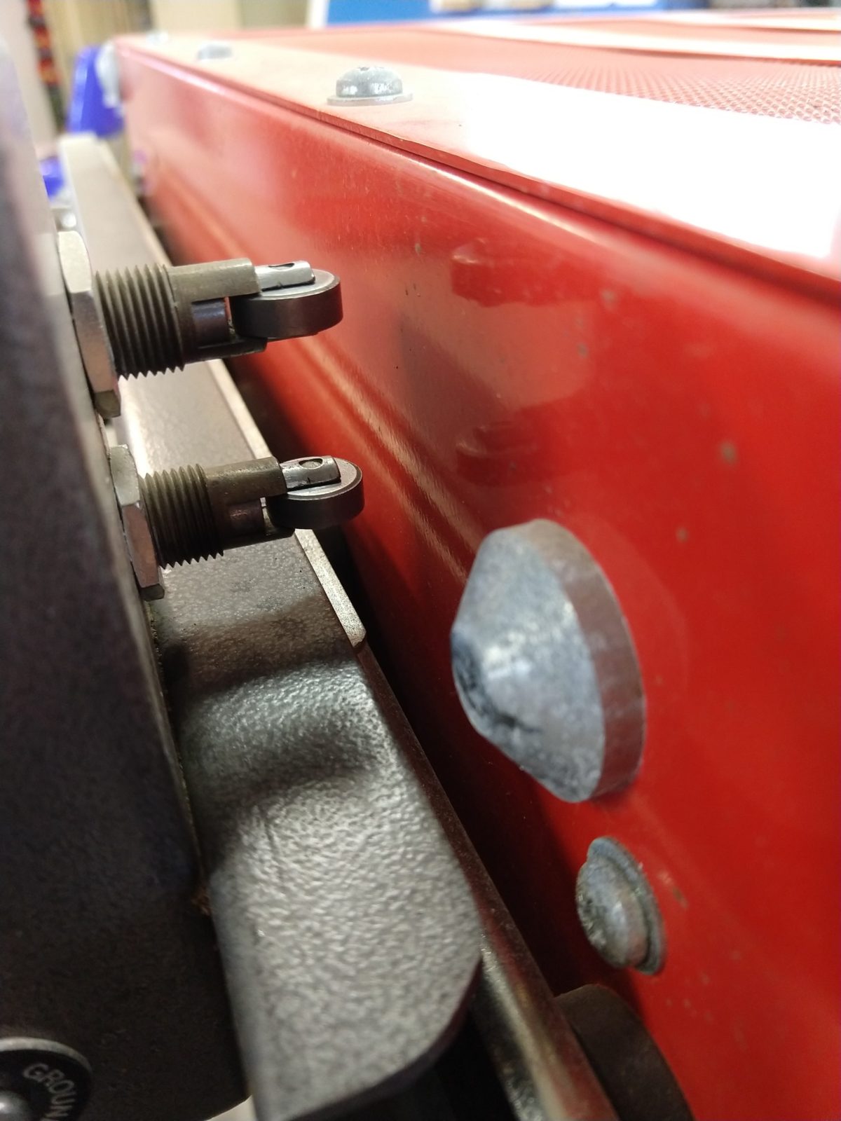
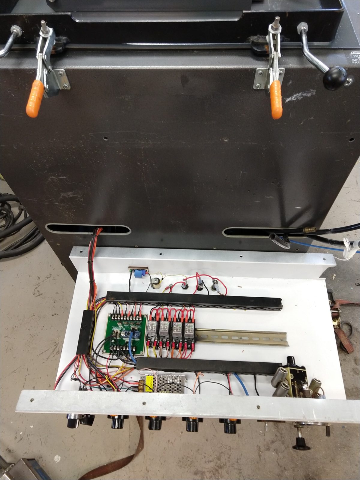
As for the timer, there are two contacts (pictured above) on the heater. When the heater slides out the lower contact starts the timer when the drawer slides are fully extended, and when it is returned home the upper contact resets the timer (also cancels the buzzer that is sounded when it hits zero). The placement of the bumps on the heater are clever and probably helps prevent people from leaving the heater in some intermediate position where it interferes with other things.
The plan:
- Replace all of the relay/timer logic with a microcontroller
- Heater controls will be replaced with potentiometers
- Extremely slow PWM to relays for heaters
- Timer display and control
- Buzzer will be kept but activated with a relay
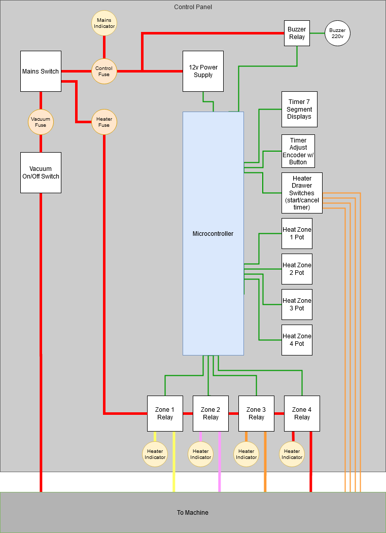
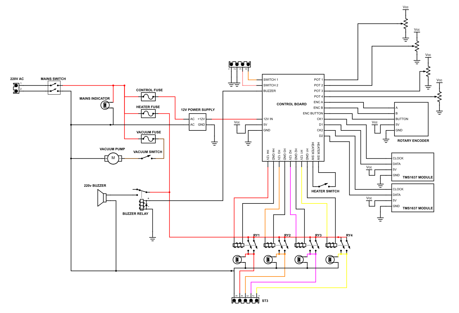
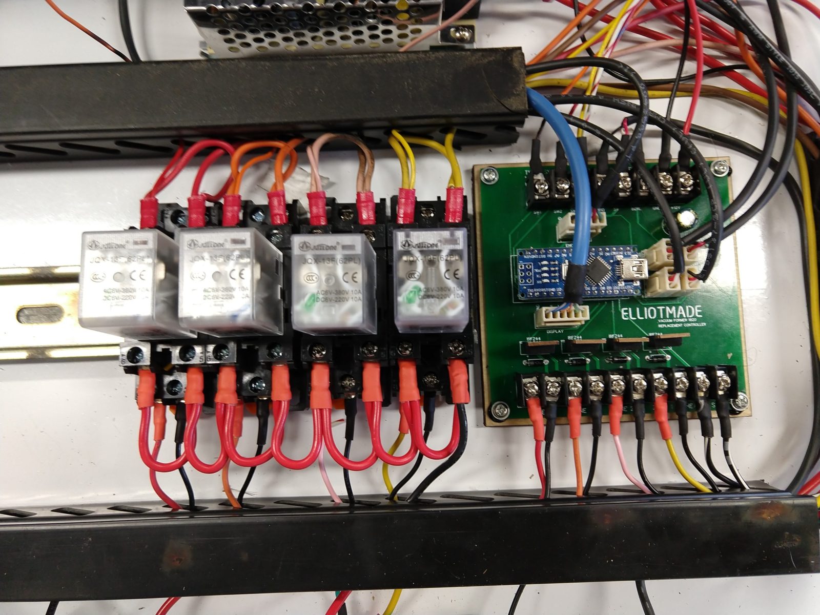
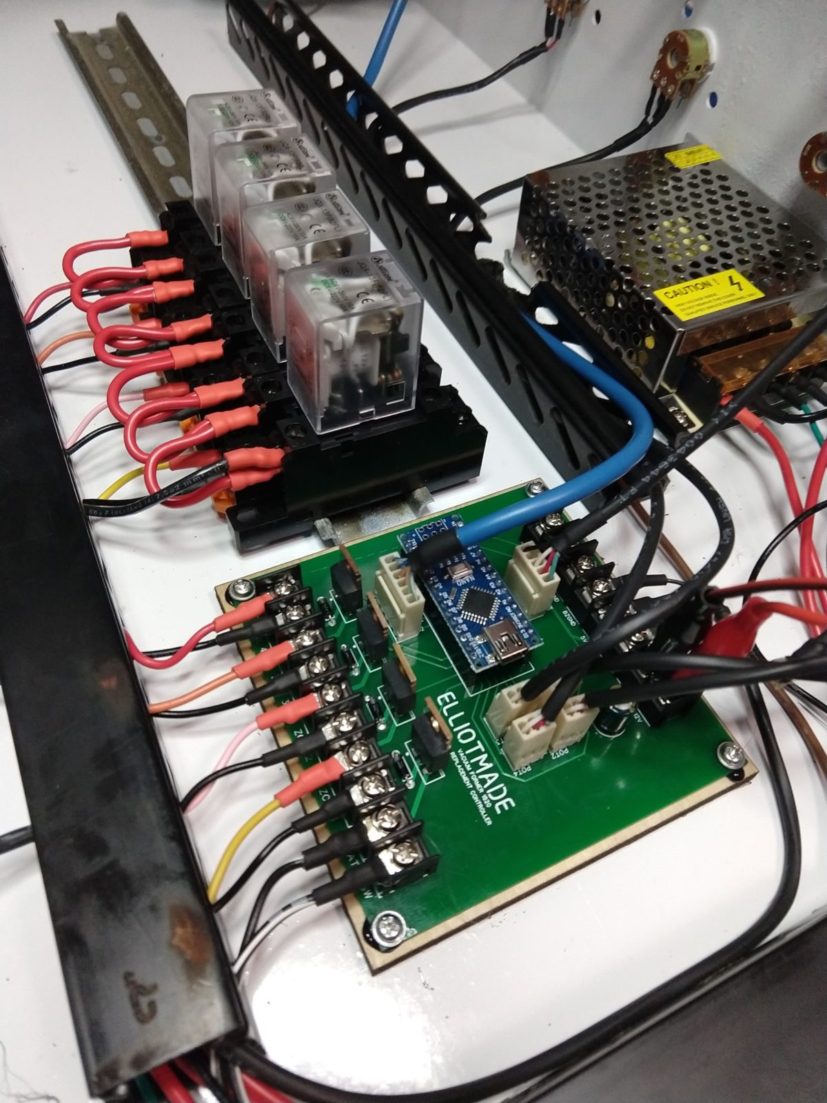
I will have to add a DC power supply for this to work, but a big benefit of that is that I can test everything out on the bench, far, far away from 220v mains. AC won’t be involved anywhere in this circuit, it will only be switched by relays:
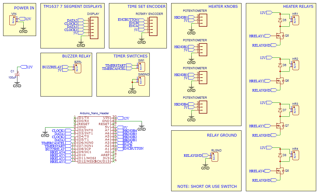
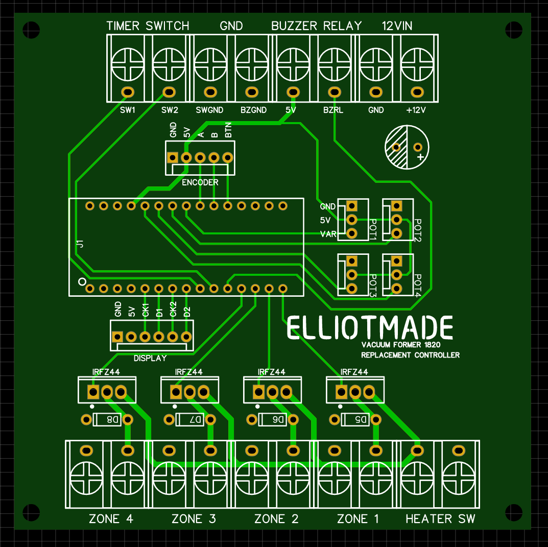
I didn’t bother prototyping this – just went ahead and ordered from JLCPCB so I will find out what mistakes I made in a few days when it gets here. The components I chose are based on what I have on hand, not that there are many of them, it’s mostly connectors. I don’t think four knobs for the heaters are really necessary, but I wanted to keep the panel the same if possible. I used potentiometers for these because I don’t have a handy way to interface five rotary encoders with an arduino nano.
Here are some more photos for future-me to reference, and I’ll post again when I make more progress!


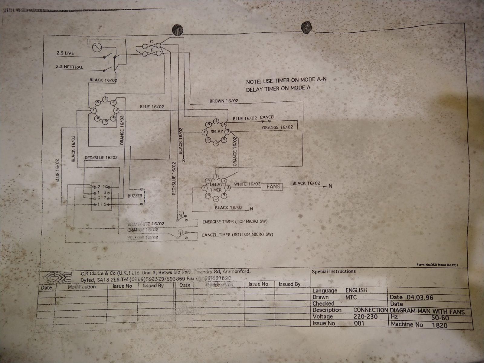
This came with it… but it didn’t help me