Wake up in the middle of the night because you’re too hot? Don’t want to spend $3000 one one of these? Not cool with a corporation controlling your sleep with a mandatory subscription? Don’t care for swamp coolers? Some other thing? This might be what you need!
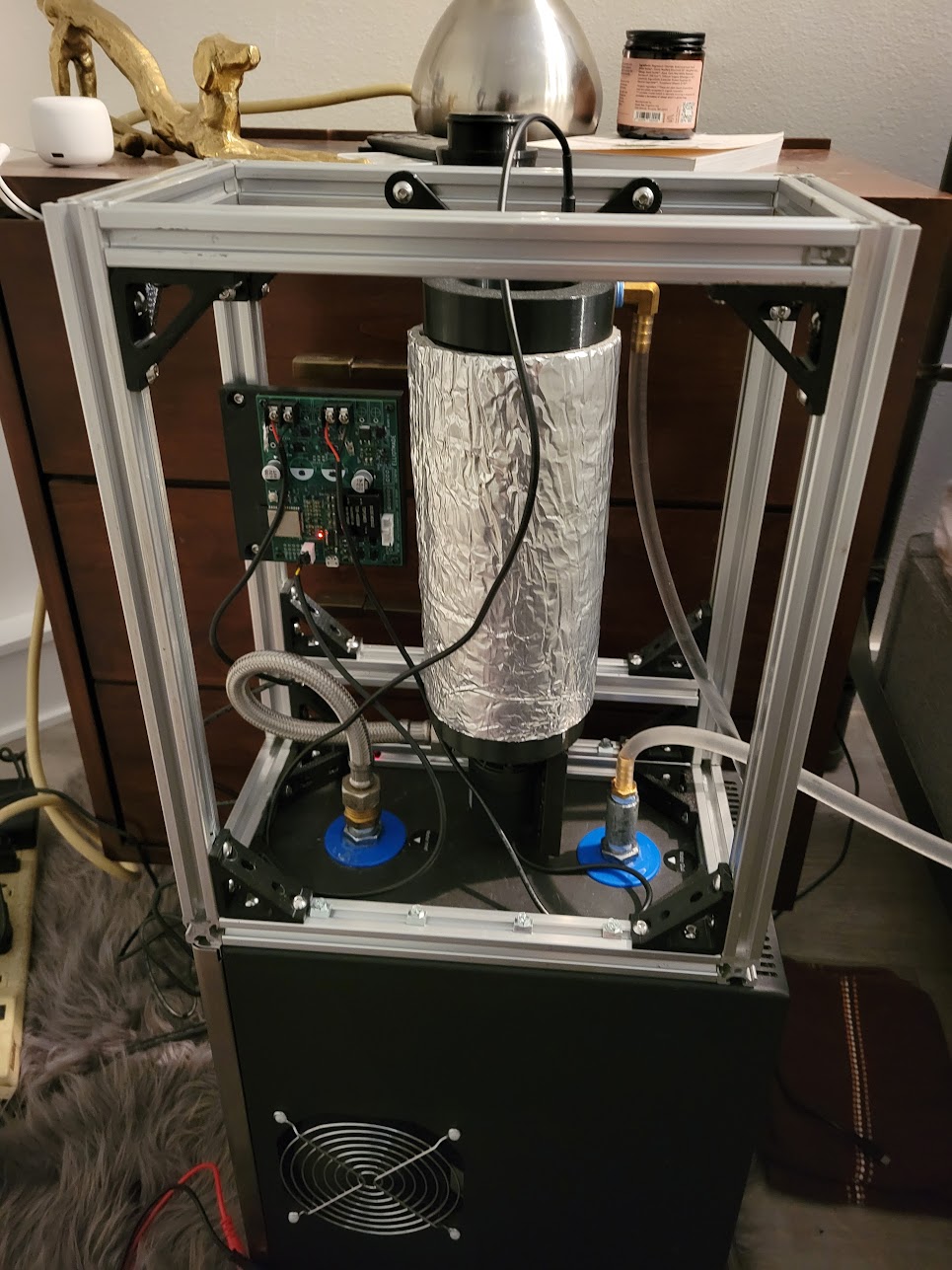
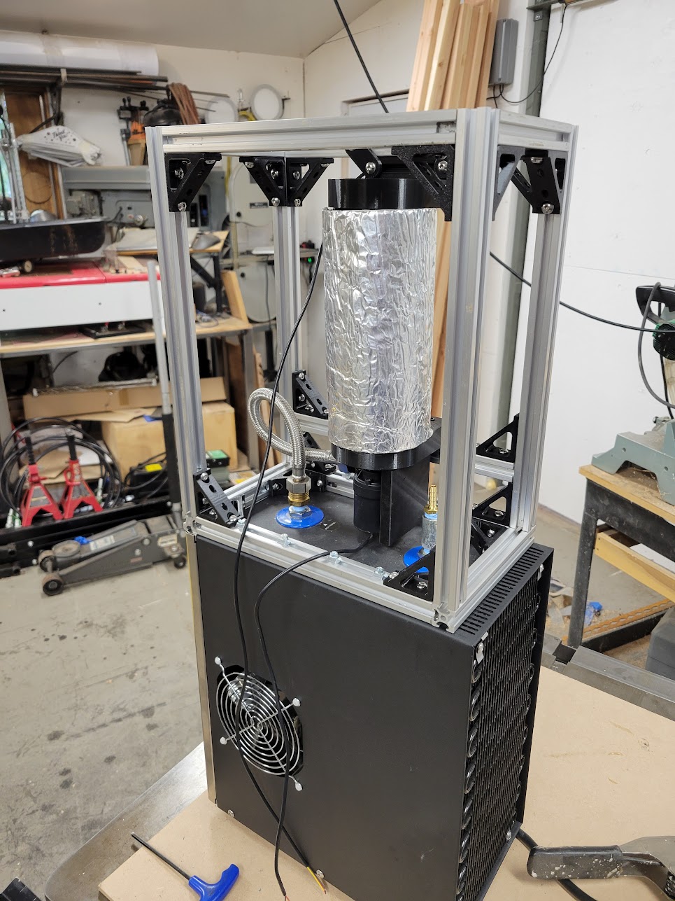
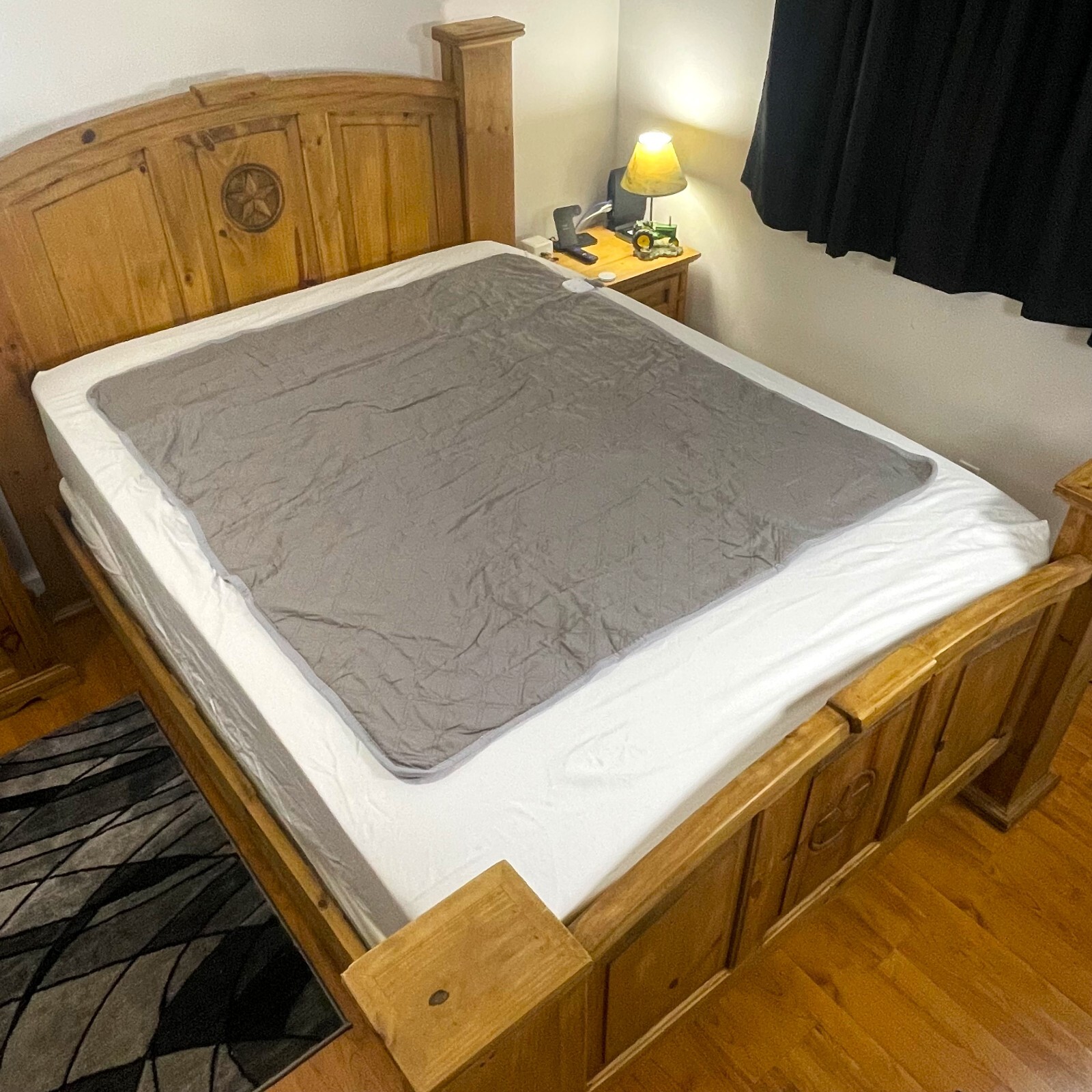
This project is a refrigerated mattress pad – mostly the cooler, I didn’t make the pad :). I purposely didn’t do a ton of research before building because figuring it out is the fun part. Most (if not all) of the products for sale that do this use a peltier cooler, swamp cooler, or only one I could find with a proper heat pump/refrigerator (which disappointingly appears to be one of these with holes in the lid and an aquarium pump). I happened upon this undersink chiller for water filters on marketplace used for $70, and for the first iteration my total cost is ~$130, but I had some parts and electronics already laying around.
First iteration
- Single zone
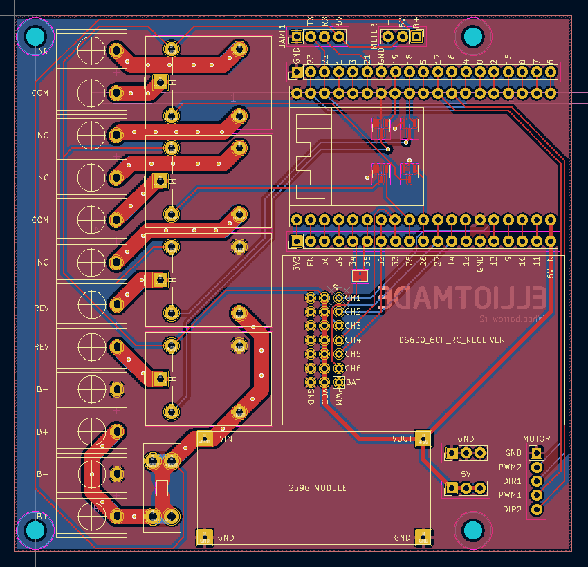
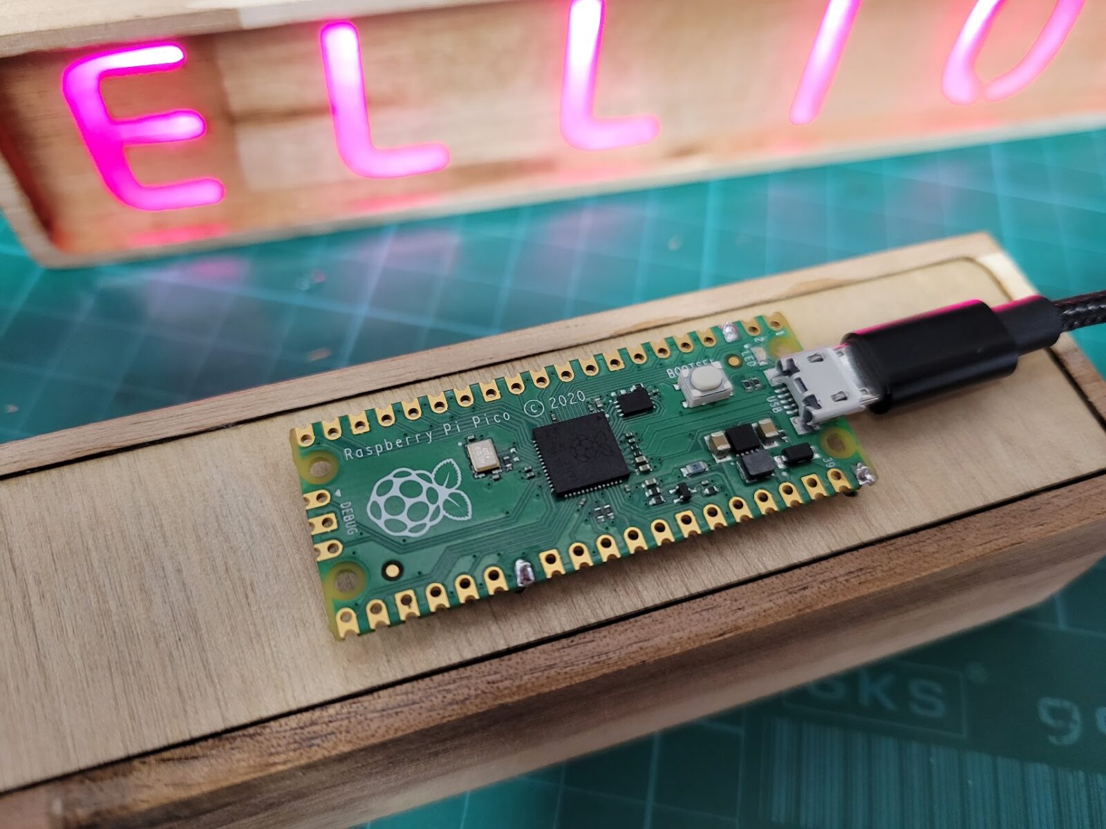
- Home assistant integration
- Fixed speed 12v pump, undervolted to reduce flow. The minimum sustained running voltage on this type of pump is lower than the startup voltage, so I kept it above that threshold.
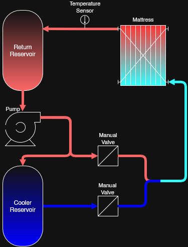
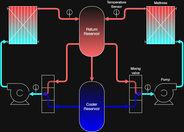
- Temperature is measured only on the return from the mattress pad
- A bypass circuit to recirculate the returning water. This can be adjusted with valves to change the mix of refrigerated and warmer return fluid.
- Temperature is regulated by cycling the pump on and off
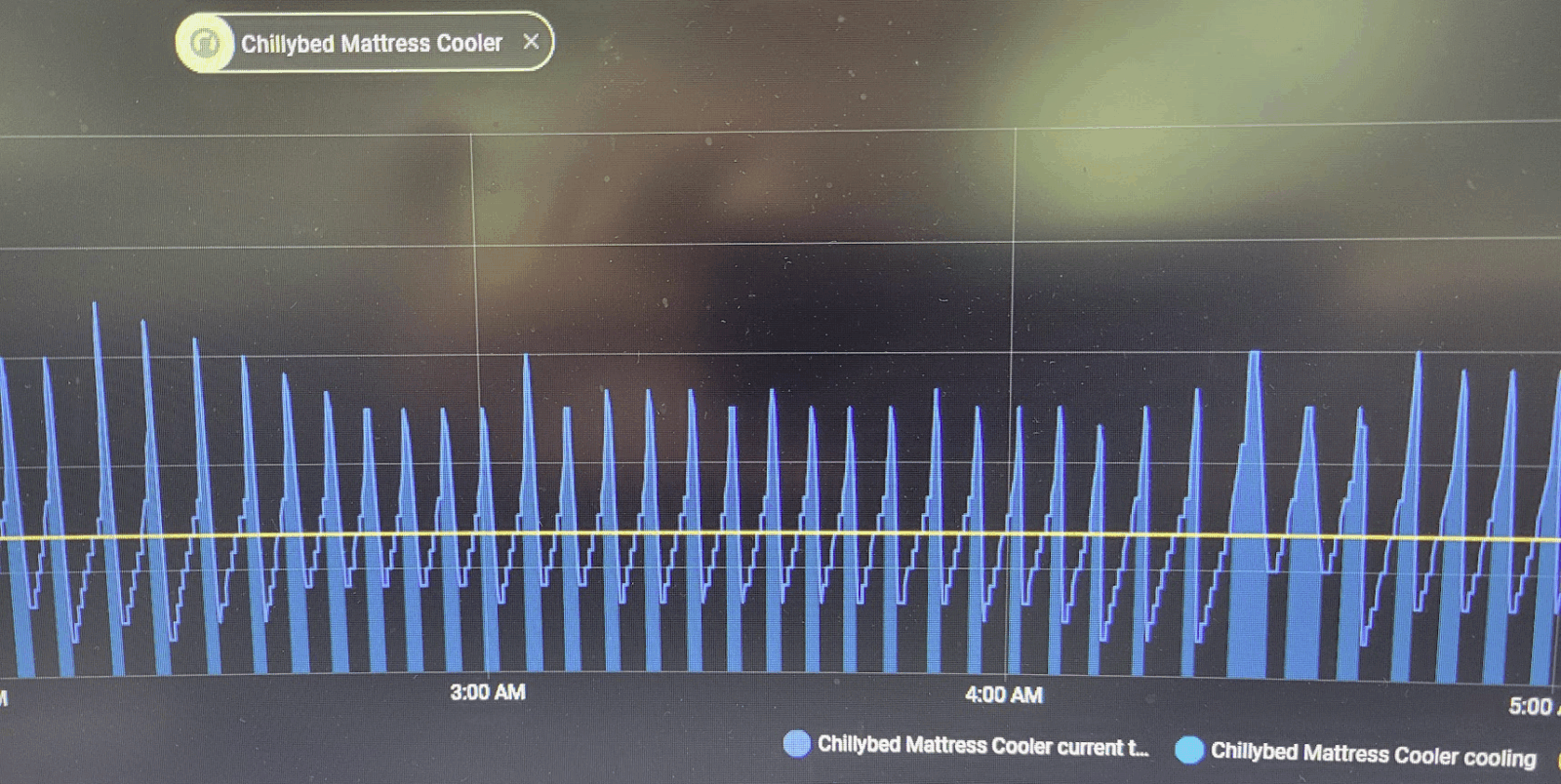
Thoughts on this arrangement: without the bypass circuit, the on-off regulation is effective but harsh. I cycle the pump in short intervals even when the return temperature is still below the target, otherwise the stagnant water in the mattress continues warming without impacting the point of measurement. Recirculating part of the un-cooled water gives some control over the output (because I’m not controlling the thermostat of the cooler itself). Here’s what that looks like (shaded areas are when the pump is active):
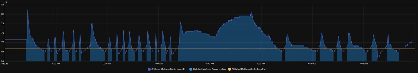
Here is the same setup after adding the bypass circuit – also the moment I realized how much heat a person can make. The less-cold water allows it to run a higher duty cycle without as severe of temperature swings:
And here is the difference with the fabric and tubing mattress pad (the two above were the PVC one):
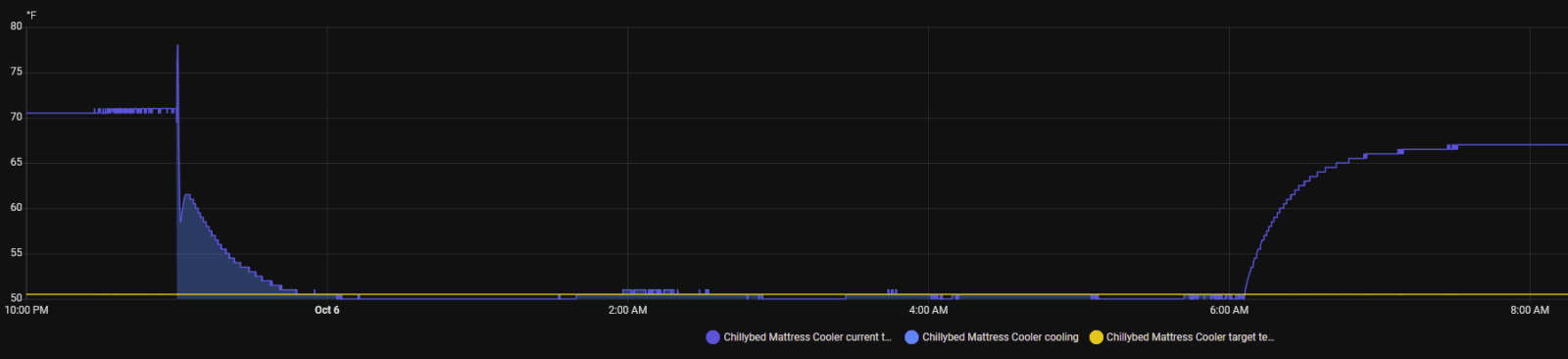
The scale on the chart is unfortunate, but notice that the target temperature is at 50 as opposed to ~70 with the PVC pad. It runs nearly continuously to maintain the low temperature, but it doesn’t absorb nearly as much heat.
Here’s what I have learned about mattress pads:
- PVC
- Excellent heat transfer. ~50 degree (f) water feels too cold, and it is very noticeable when the pump starts and stops. Continuous cooling is way too cold for comfort.
- Feels like plastic, but is still effective with a towel or other fabric between the pad and your sheets.
- https://www.amazon.com/Cooling-Mattress-Without-Sleepers-Perfectly/dp/B0F2FGKHJL
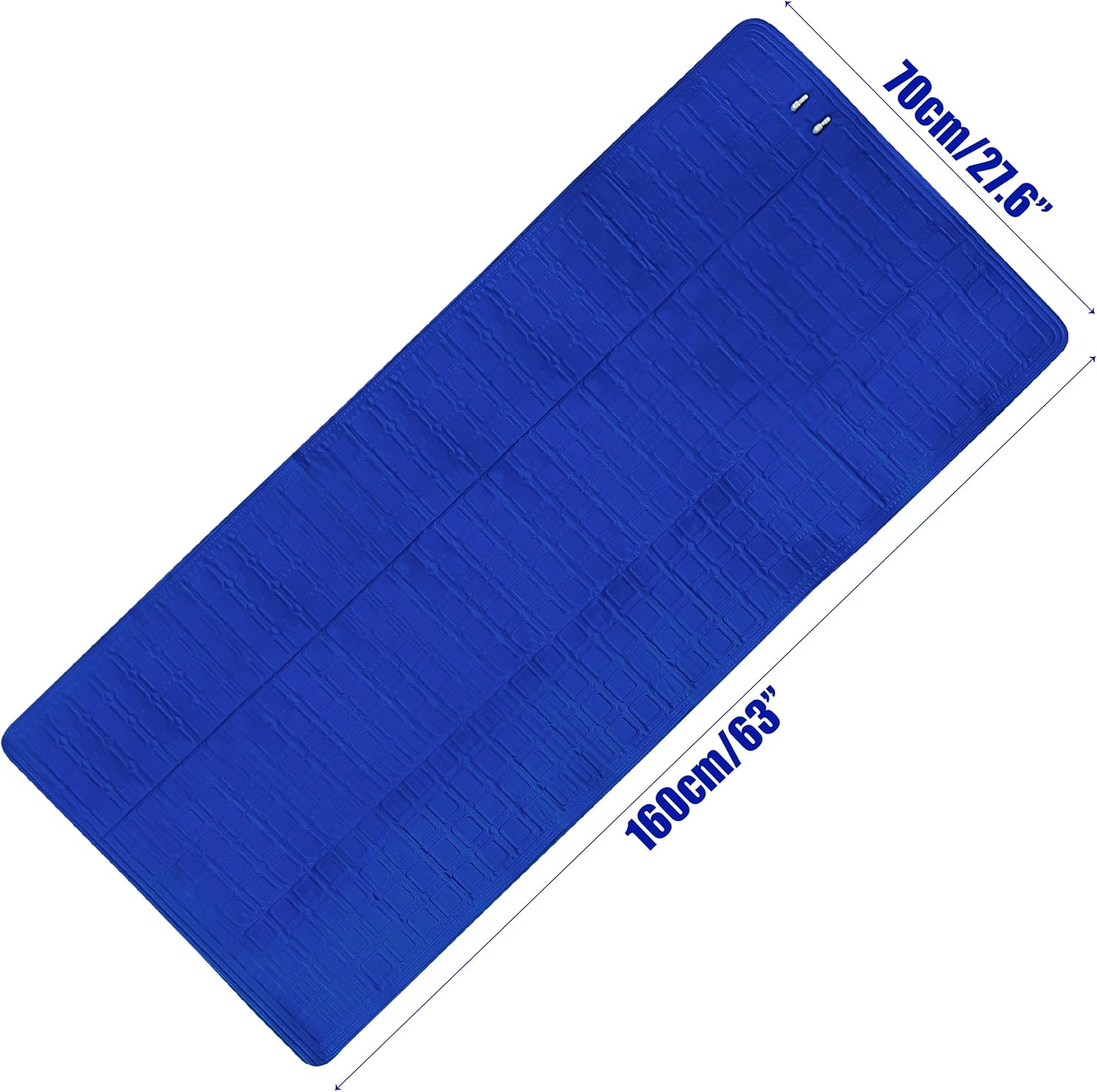
- Fabric with tubing sewn in
- Can feel the tubes, but still fairly comfortable
- Poor heat transfer. Can continuously circulate ~50 degree water all night without getting too cold. It does keep you cool, but can be overwhelmed by two warm people or one hot flash
- https://www.ebay.com/itm/297280172377?var=594842370702
Other considerations
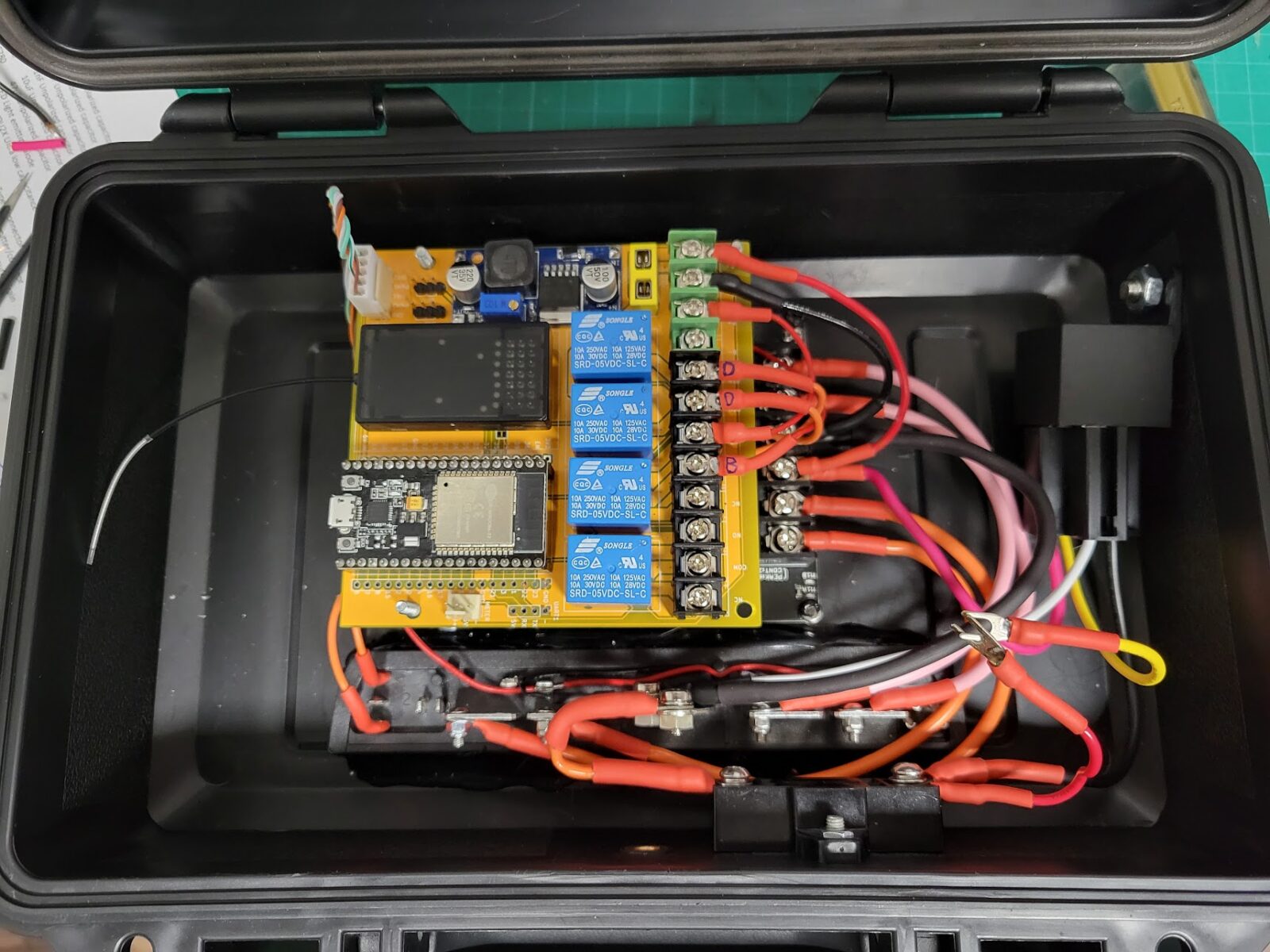
Noise: not so bad. It’s basically a tiny refrigerator, imagine having a mini-fridge in your bedroom. It’s much quieter than a window AC unit. The dominant sound is the chiller. The pump was audible when run at full voltage, but is very quiet at around 8 volts. I did try PWM’ing the pump, but it’s already a brushless motor so the control was not great and it squealed in an unhappy way.
Leaks: none so far. I used dry-break quick disconnects, so unhooking it to make the bed is no big deal. I Haven’t had to add water since the initial fill – the reservoir is not 100% airtight, but evaporation should be minimal due to the small surface area exposed to air.
Second iteration – what I will do next
Feedback has been overwhelmingly positive, so it warrants improving. The two major improvements I want to make are: dual-zone (separate circuits) and more clever temperature regulation. Here’s the plan:
- Add a separate circuit, complete with it’s own mattress pad, circulating pump, and temperature control
- Measure both output and return water temperatures and implement a better control loop
- Actively regulate the output water temperature independent from the circulation. Like a shower valve that can mix hot and cold, but this will be actuated electronically
- Update the home assistant integration accordingly
Conclusion
This post is just my notes for now, hopefully I’ll update it with more photos and details. I will also document this project on github at some point and include the 3d-printable parts, probably after I refine the mixing valve design.