In this post I’ll share my implementation (so far) of an approach to find the distance and direction of a beacon, with an end goal of building a human following robot. It’s not an original idea – here is an earlier project by Ben Heck and Jesse Robinson that does the same thing. Check the bottom of this post for a quick video demo of the thing.
The setup
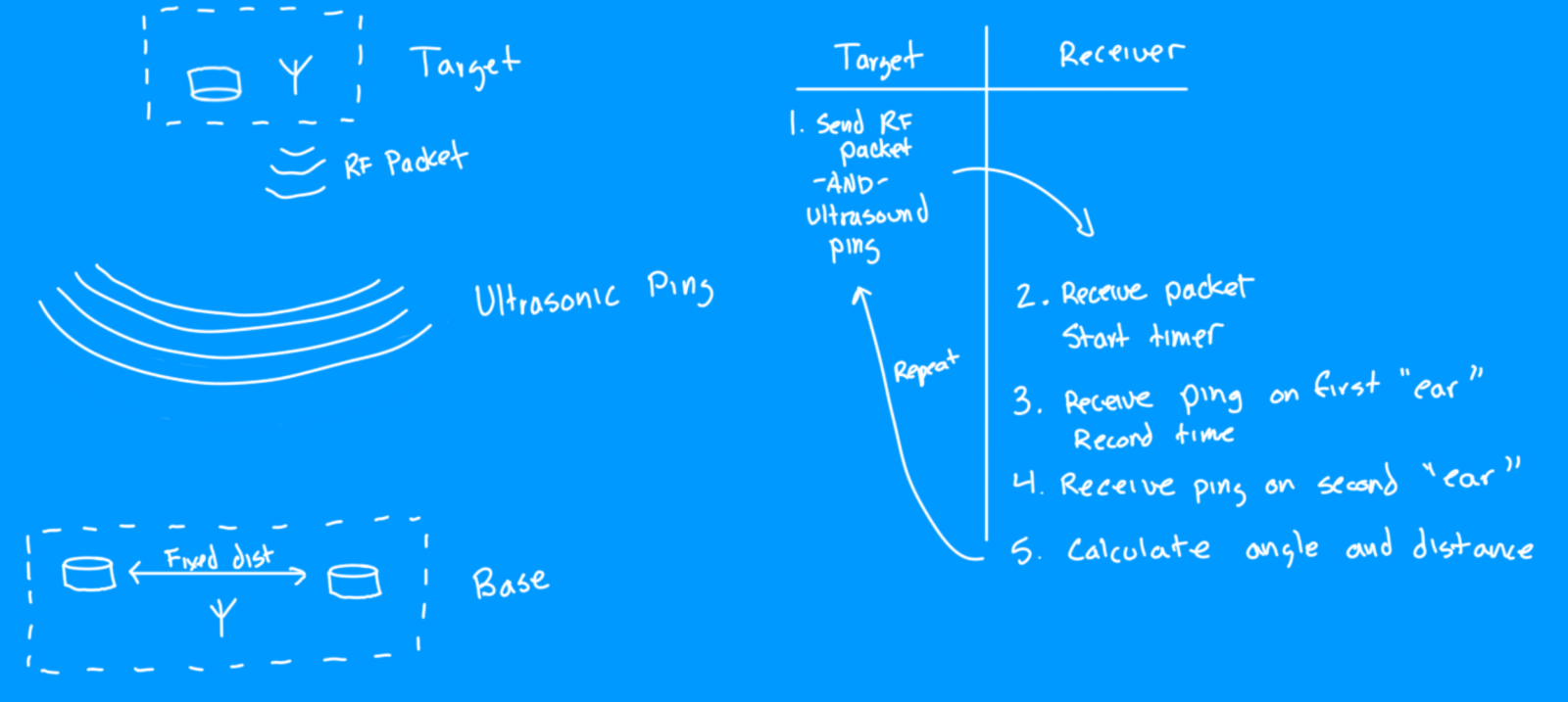
The simple idea is to have a beacon that emits a 40kHz “ping” and a pair of receivers – by comparing the difference in arrival time at each receiver, the angle to the beacon can be calculated. For the distance measurement, a radio signal can be used to synchronize the beacon with the receiver, the difference between when the RF and sonic pulse corresponds to the distance.
What makes this a hack
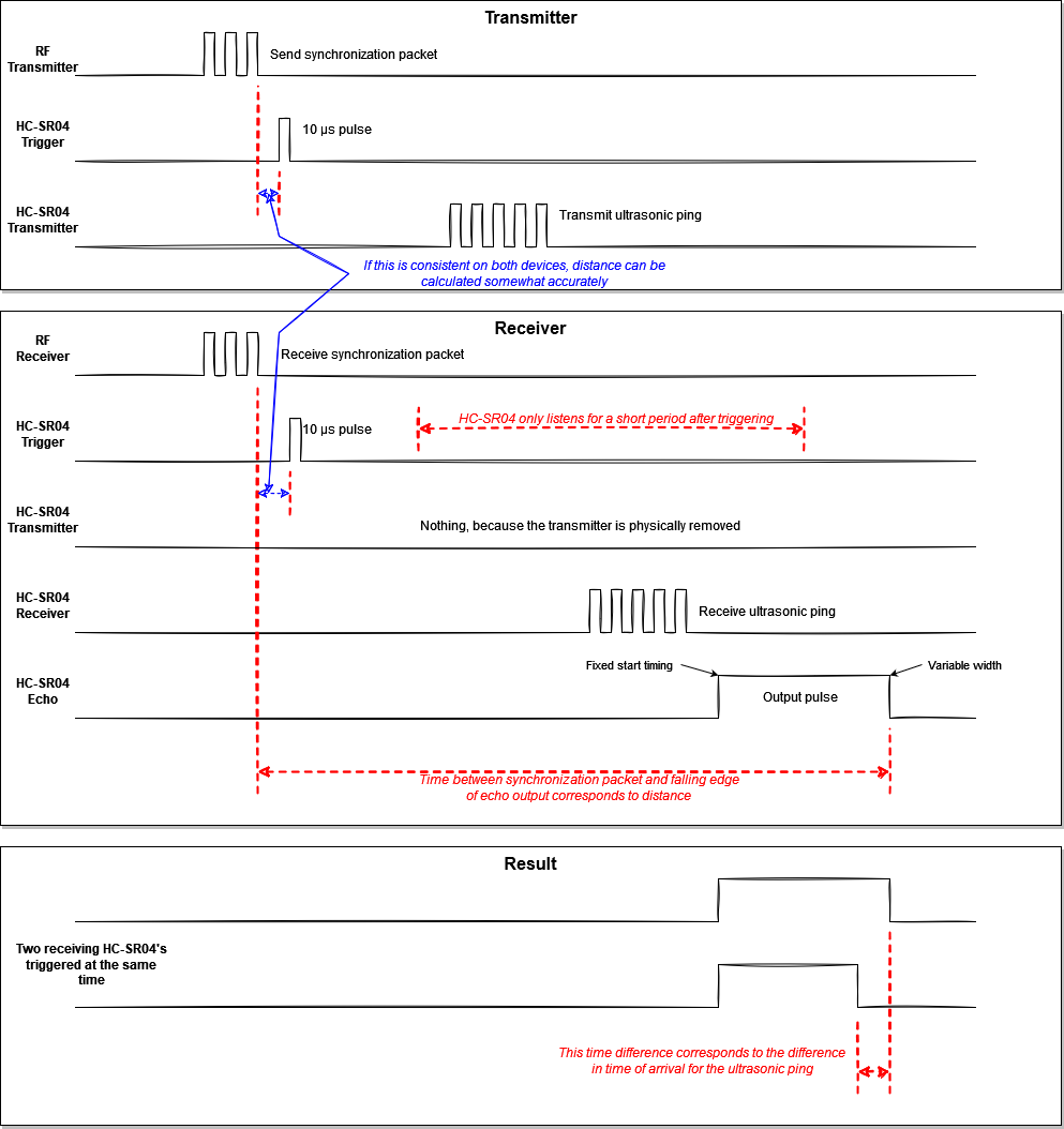
The fun thing here is using common “HC-SR04” modules in a way they weren’t intended. Normally these devices send out a pulse when they are triggered, listen for the echo, and output a pulse with a varying width that corresponds to a distance measurement. The receiver is only active for a short period of time after it is triggered, making it nearly useless for passive listening unless you trigger repeatedly and rapidly – it also would be transmitting pings and filling the environment with noise and echoes.
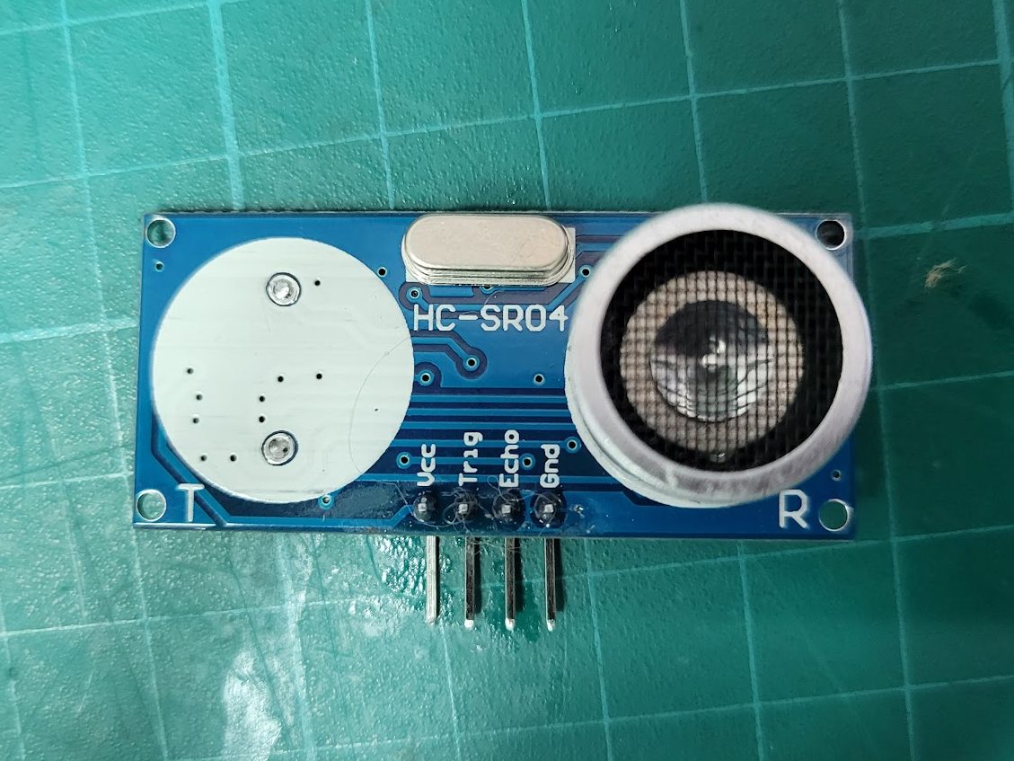
The first “hack” part is easy – desolder the transmit transducer from the module – now it can’t transmit anything and gives a short window for receiving. The second part is to synchronize the trigger for the receivers with the transmission from the beacon, so that hopefully the incoming ultrasonic wave hits within the “listening” time window. A radio signal works great, relative to ultrasound we can pretend it is instantaneous and use it to align all of the events.
One important factor is the execution time for code on the microcontrollers that are running the show. It is best if interrupts can be used – ideally the amount of time between receiving the radio signal and triggering the modules is deterministic/repeatable – this way a consistent reading can be made for distance. In my test using a 433mhz radio I found the timing was very reliable; using the ESP-NOW protocol with the ESP-32 introduced about 200 microseconds of variability, which is not ideal, but only creates a couple of inches of distance error which is OK for the ranges I expect to use it at.
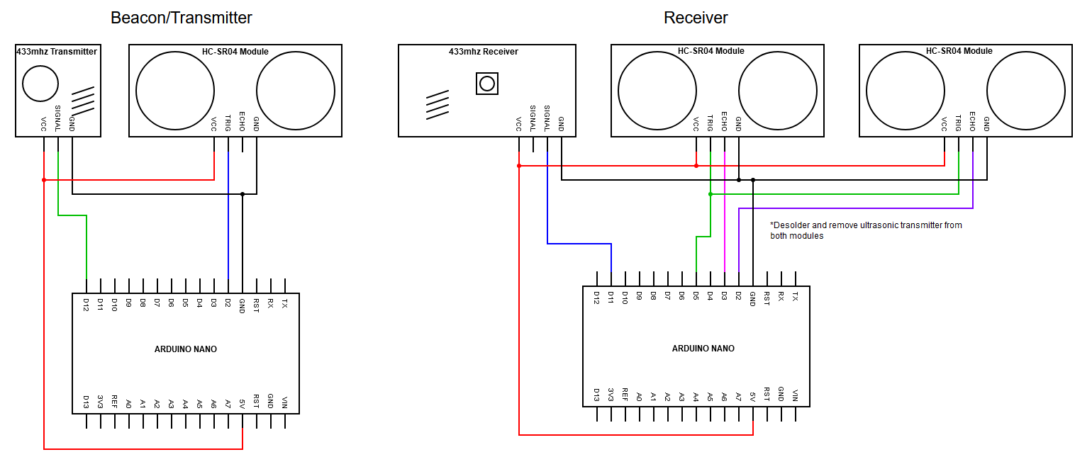
Wiring
Here is the first version I created with two Arduino Nanos:
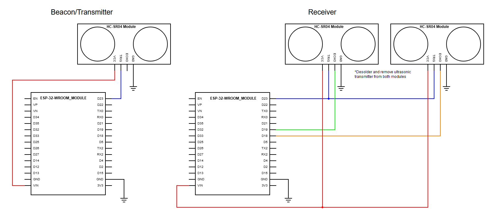
And here is the second version with two ESP-32 modules
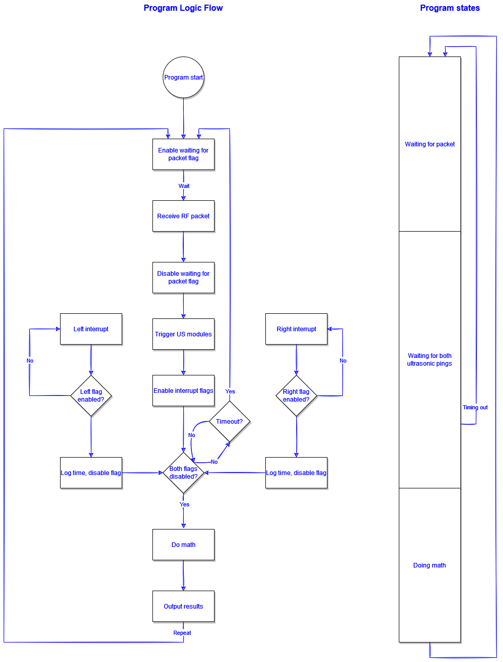
Program
This is the basic logic of the receiver – basically it starts a timer when a RF signal is received, then records the time when the ultrasonic ping is received at each receiver. Some math is done, then we have the distance and angle. The transmitter is even simpler, it just blindly fires off packets and pings repeatedly.
Code
Below is a zip file with four platformio projects in subfolders. There is a pair for the arduino and a pair for the ESP32. I didn’t do a great job on these, but I think they suffice to demonstrate the concept.
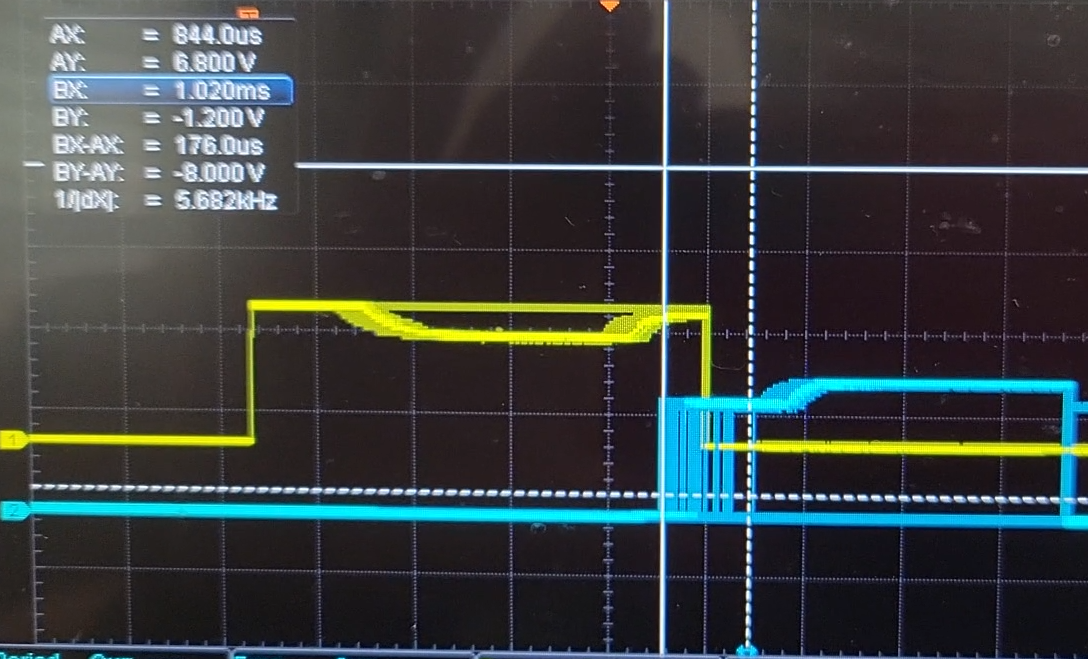
Result
The performance is pretty good in my opinion, but not without some limitations. The angle resolution is quite good from about 2 feet to 30 feet. I don’t have good data on the ranging accuracy at longer distances, but it seems to be reliable within to a few inches – more testing is needed. It is susceptible to obstructions and echoes, as well as line of sight – the receivers and transmitter only work within about an 80 degree cone, so they must be pointed at each other to work. Software filtering would be a good idea to smooth out the readings. Here’s a quick video of my preliminary results – I haven’t implemented any safety features or tried to handle loss of signal just yet: