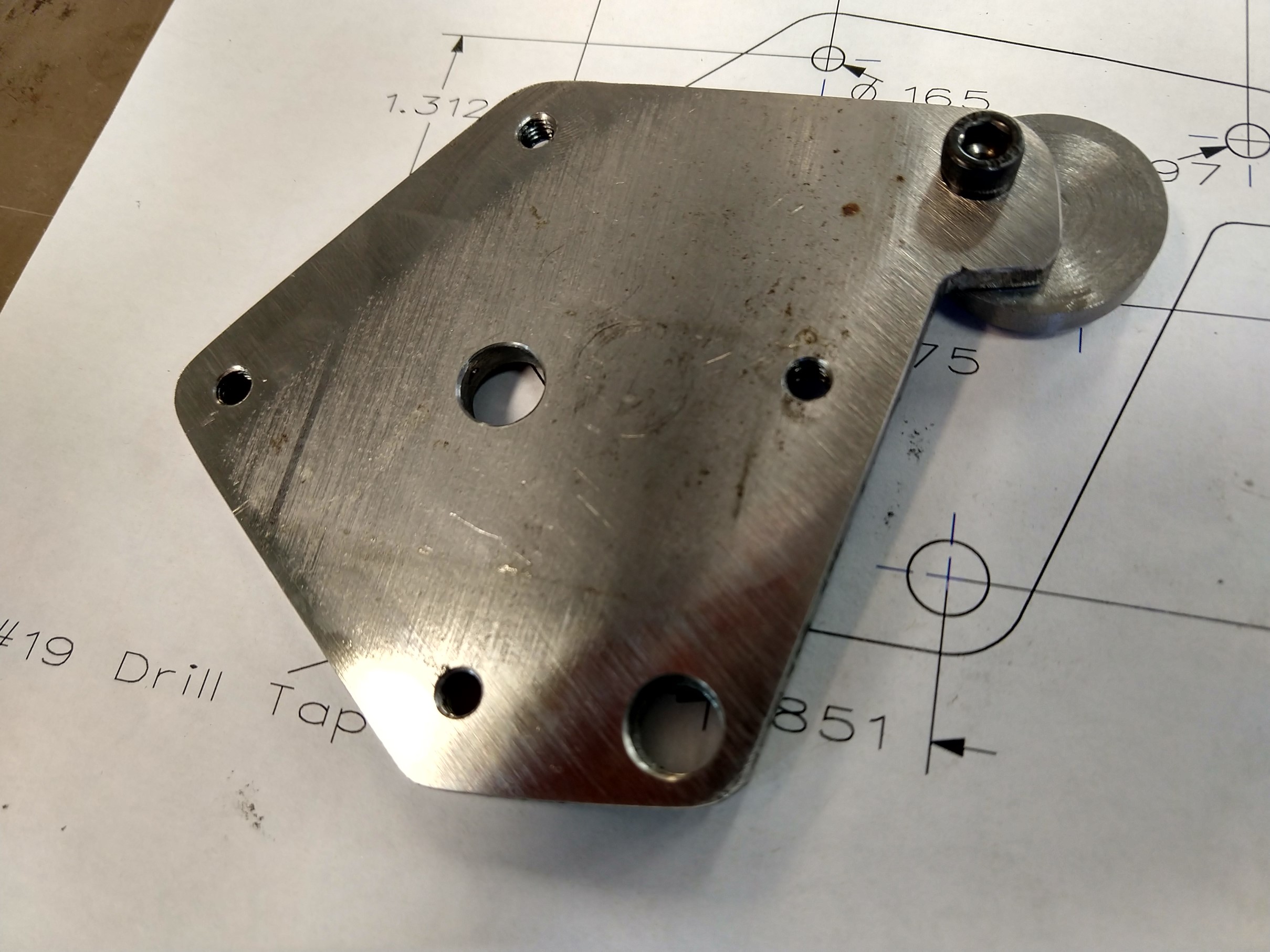
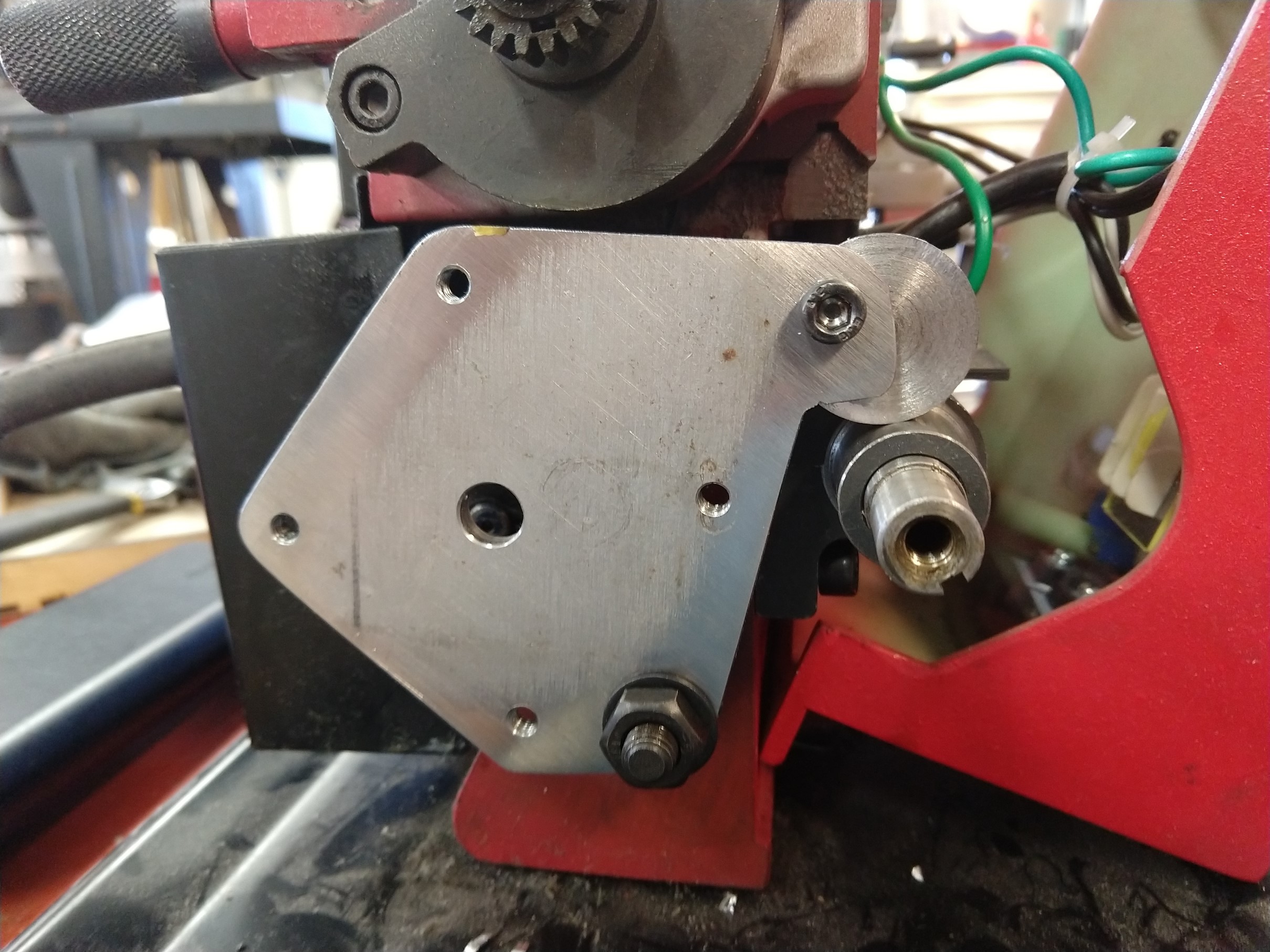
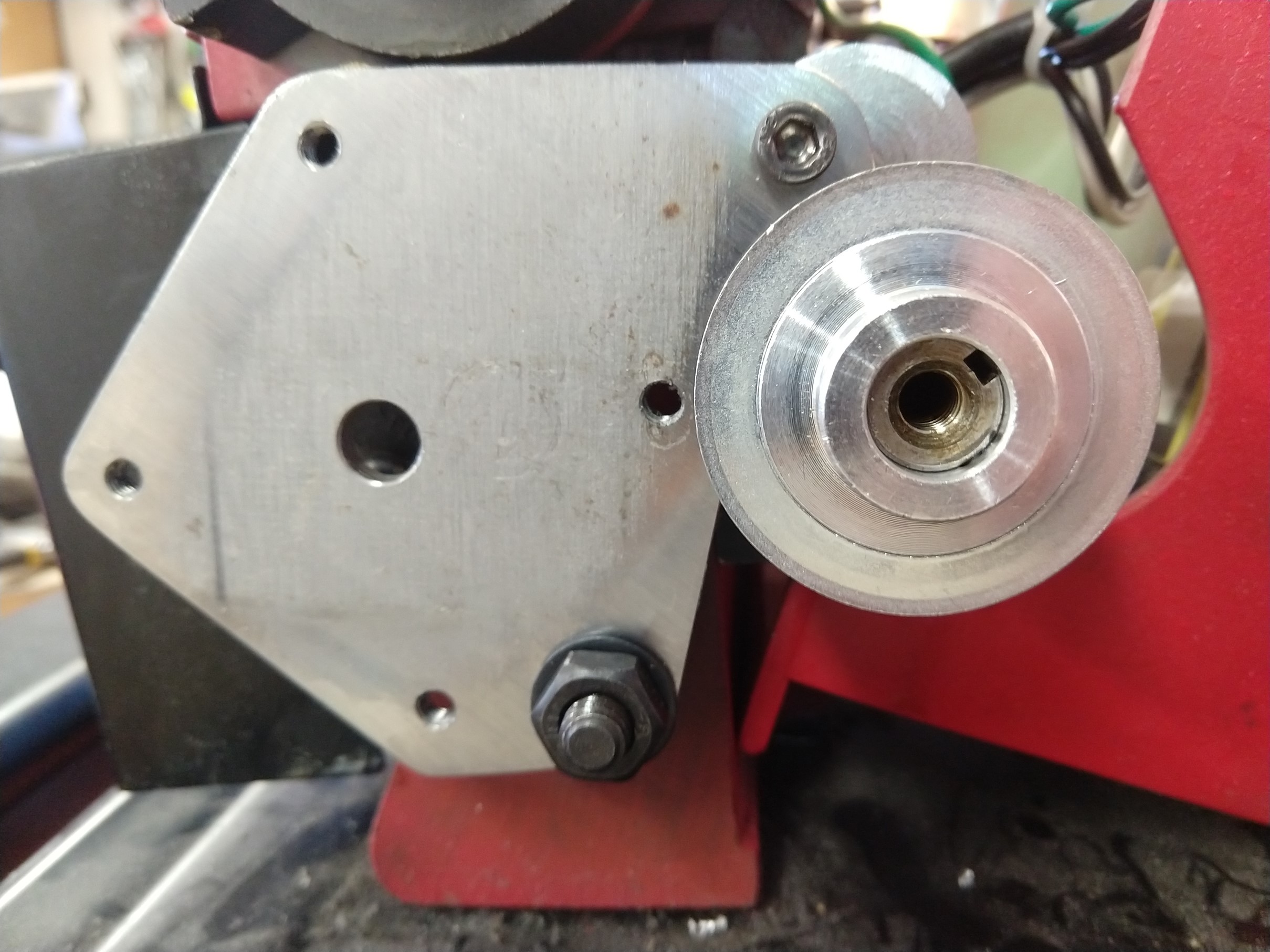
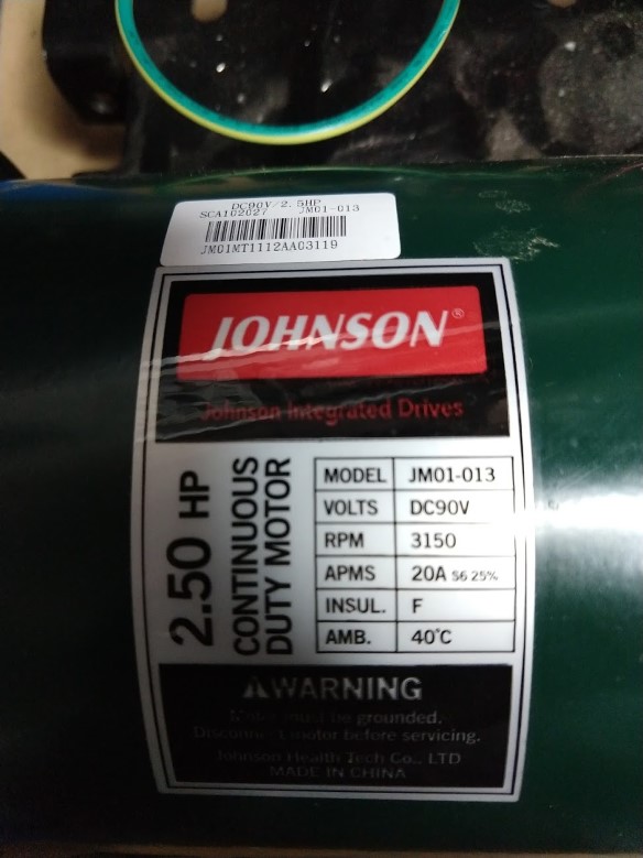
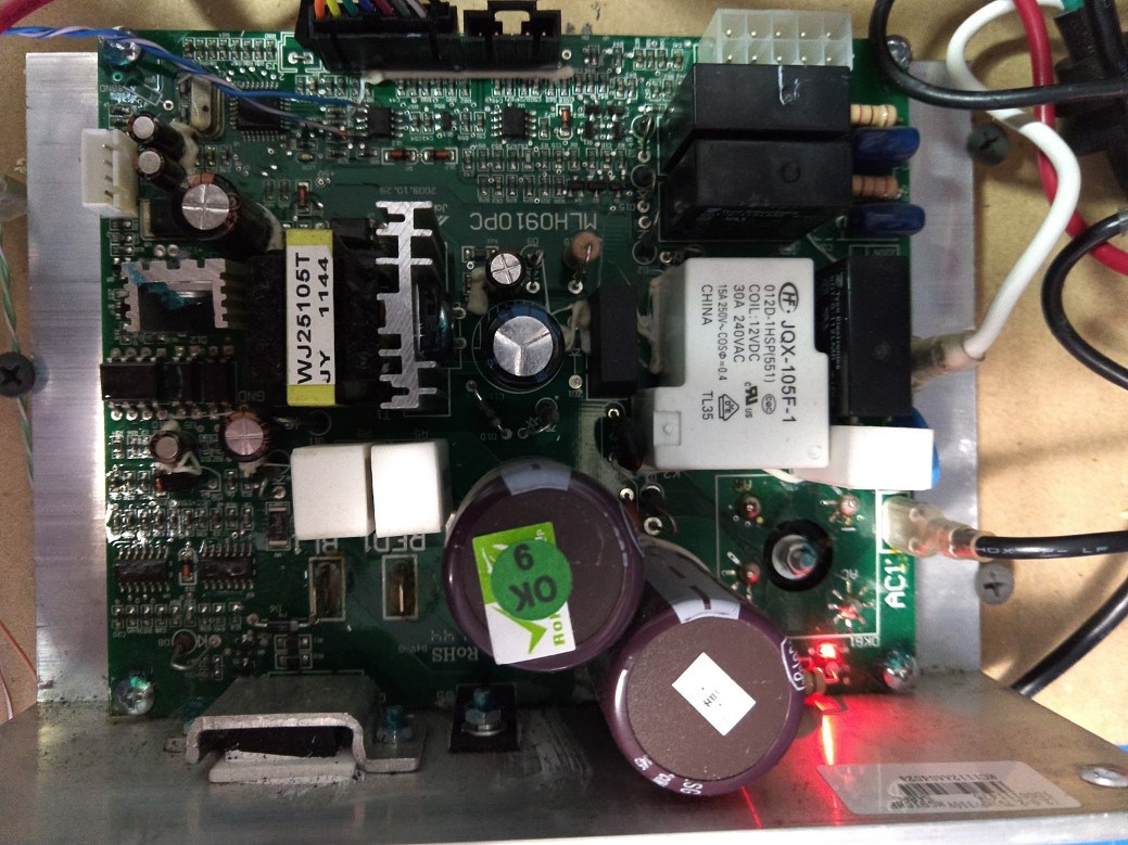
I scrapped a treadmill and salvaged the motor for a belt grinder project. My goal is to chuck the original control panel and just use the motor and it’s controller… but unlike the previous treadmill I did this to, interfacing with this one was not as simple as feeding it a PWM signal. The motor is a Johnson 90v DC motor, model JM01-013, and the control board is labeled MLH0910PC. I’m hoping the following information helps at least one other person – I spent hours searching and wasn’t able to come up with anything useful.
The control panel (I’ll refer to this as the panel going forward) has all of the displays and connects to the rest of the interface buttons and the safety key switch. The motor controller contains the AC connection, runs the motor and incline, as well as supplies power for the panel.
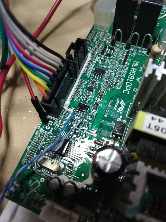
There is a single cable connecting the controller and panel with 8 wires: two are the safety key switch and pass straight through to the controller, two for power, two for ground, and the last two are for serial data. On both ends of the connector there is a MAX3085 RS-485 transceiver chip. Initially I used a MAX485 on a breakout board to listen in, but I was struggling to extract useful data with a logic analyzer and PulseView. It was clear that there was a message and response from one unit to the other, but for whatever reason I wasn’t able to reliably pick up the start and end bits for the response. I had much better luck connecting the logic analyzer directly to pins 1 and 4 of the MAX3085 (on either board works)… this let me see the RX and TX data on separate channels, then it could be decoded easily.
From what I can tell the panel is the master, it always initiates communication (either a command or a query), and the controller only responds. Messages are sent roughly every 70-100 ms at 9600 baud and consist of 5-7 bytes. The first two bytes look like an identifier: the panel prefix is 0-255, and the controller is 0-127. I looked at all of this in decimal because why not, also it made it easy to work with in Excel. I was able to isolate the packet from the panel that seemed to control the speed, then I recorded the values for every speed available from .5 to 12 MPH in tenth of a MPH increments.
I used an arduino to replay all of the messages through the MAX485 from power-up to running and was pleased to see the motor start to run (I kept the safety switch shorted). Working backwards, I started eliminating the different messages until all I had left was the speed command and the motor continued to run – showing me that I can ignore pretty much everything else – great! Did some more experimentation and here is what I found:
- Only speed commands are needed
- All acknowledgements from the controller can be ignored
- Any new speed lower than the current one will be accepted by the controller and it will coast down to that setting
- A new speed higher than the current one will be accepted if it is not too much higher. For example, the motor will accelerate from 5 to 5.1 mph
- A new speed too much higher than the current one will be rejected and the motor will coast to a stop. For example, commanding it to accelerate from 5 to 12 mph.
- Speed changes are very gradual (probably to keep you from falling on your face and/or butt)
- It won’t exceed 4000 RPM (12 mph), or perhaps I picked bogus values when I tried
This means that interfacing with this is going to be pretty easy. My approach was just to create a lookup table for the known speeds that I mapped out. When increasing the speed I ramp through each of the steps on the way to the final target speed, this seems to keep the controller happy and it doesn’t panic and coast to a stop. There is no need to ramp down to a slower speed, only to a higher one.
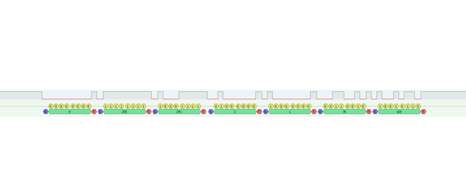
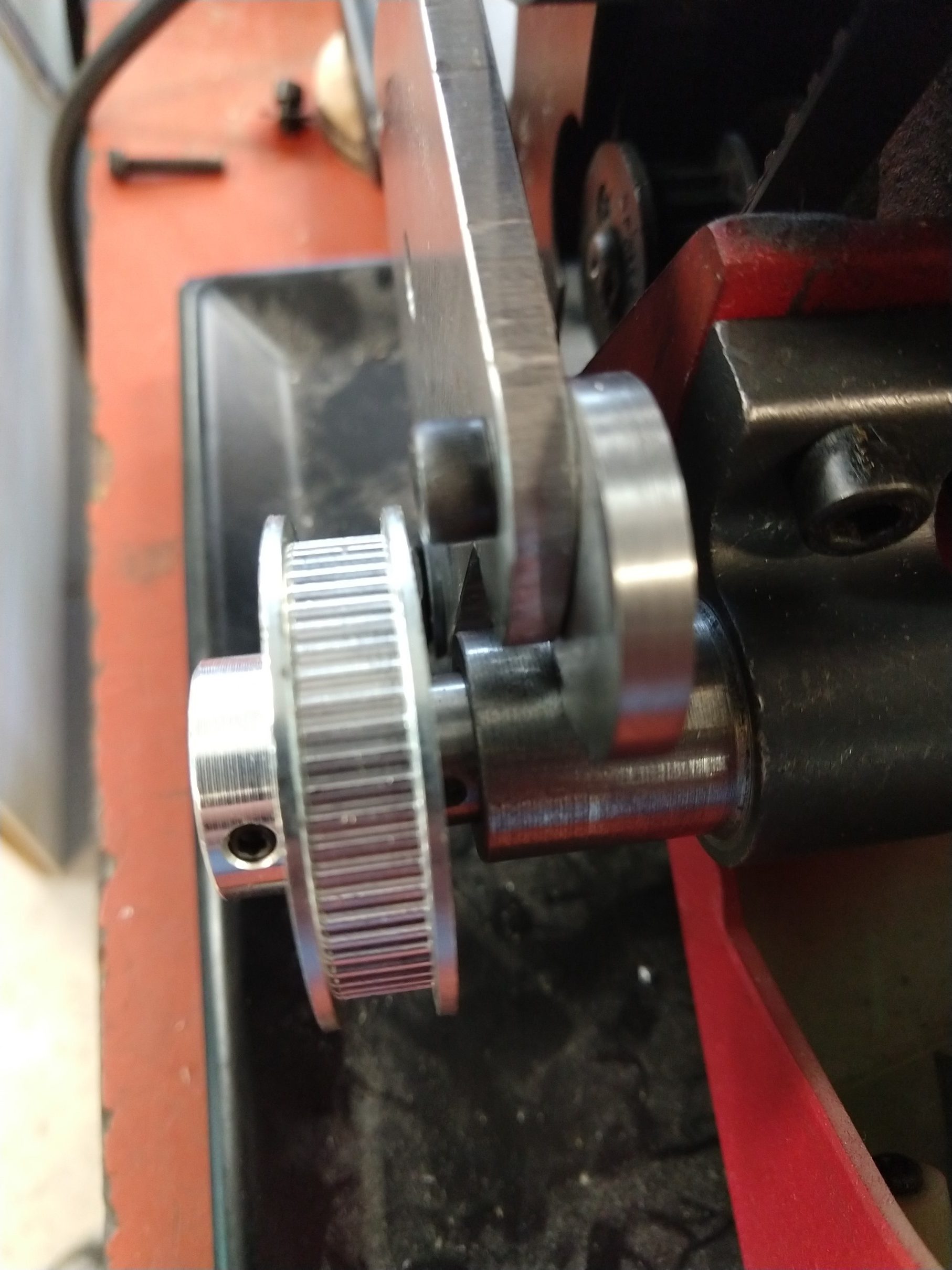
The 7-byte packet that controls speed is pictured above. I mapped all of the speeds from zero to twelve MPH, see the table below. RPM was measured with no load, but I expect it to be similar under load – the motor has a toothed wheel (maybe optical or probably hall-effect) and I’m guessing it uses closed-loop speed control.
Mission accomplished! I’ve actually had this motor sitting around for over a year but never made any headway on figuring out how to control it, now I can move on and make something useful with it.
| MPH | Byte 1 | Byte 2 | Byte 3 | Byte 4 | Byte 5 | Byte 6 | Byte 7 | Measured RPM |
|---|---|---|---|---|---|---|---|---|
| 0.0 | 0 | 255 | 241 | 2 | 0 | 0 | 221 | 0 |
| 0.5 | 0 | 255 | 241 | 2 | 0 | 161 | 16 | |
| 0.6 | 0 | 255 | 241 | 2 | 0 | 195 | 201 | |
| 0.7 | 0 | 255 | 241 | 2 | 0 | 230 | 186 | |
| 0.8 | 0 | 255 | 241 | 2 | 1 | 8 | 144 | |
| 0.9 | 0 | 255 | 241 | 2 | 1 | 42 | 116 | |
| 1.0 | 0 | 255 | 241 | 2 | 1 | 76 | 105 | 332 |
| 1.1 | 0 | 255 | 241 | 2 | 1 | 111 | 188 | |
| 1.2 | 0 | 255 | 241 | 2 | 1 | 145 | 33 | |
| 1.3 | 0 | 255 | 241 | 2 | 1 | 179 | 197 | |
| 1.4 | 0 | 255 | 241 | 2 | 1 | 213 | 216 | |
| 1.5 | 0 | 255 | 241 | 2 | 1 | 248 | 18 | |
| 1.6 | 0 | 255 | 241 | 2 | 2 | 26 | 156 | |
| 1.7 | 0 | 255 | 241 | 2 | 2 | 60 | 188 | |
| 1.8 | 0 | 255 | 241 | 2 | 2 | 94 | 101 | |
| 1.9 | 0 | 255 | 241 | 2 | 2 | 129 | 79 | |
| 2.0 | 0 | 255 | 241 | 2 | 2 | 163 | 171 | 670 |
| 2.1 | 0 | 255 | 241 | 2 | 2 | 197 | 182 | |
| 2.2 | 0 | 255 | 241 | 2 | 2 | 231 | 82 | |
| 2.3 | 0 | 255 | 241 | 2 | 3 | 10 | 43 | |
| 2.4 | 0 | 255 | 241 | 2 | 3 | 44 | 11 | |
| 2.5 | 0 | 255 | 241 | 2 | 3 | 78 | 210 | |
| 2.6 | 0 | 255 | 241 | 2 | 3 | 112 | 8 | |
| 2.7 | 0 | 255 | 241 | 2 | 3 | 147 | 154 | |
| 2.8 | 0 | 255 | 241 | 2 | 3 | 181 | 186 | |
| 2.9 | 0 | 255 | 241 | 2 | 3 | 215 | 99 | |
| 3.0 | 0 | 255 | 241 | 2 | 3 | 249 | 250 | 1016 |
| 3.1 | 0 | 255 | 241 | 2 | 4 | 28 | 96 | |
| 3.2 | 0 | 255 | 241 | 2 | 4 | 62 | 132 | |
| 3.3 | 0 | 255 | 241 | 2 | 4 | 96 | 229 | |
| 3.4 | 0 | 255 | 241 | 2 | 4 | 130 | 70 | |
| 3.5 | 0 | 255 | 241 | 2 | 4 | 165 | 87 | |
| 3.6 | 0 | 255 | 241 | 2 | 4 | 199 | 142 | |
| 3.7 | 0 | 255 | 241 | 2 | 4 | 233 | 23 | |
| 3.8 | 0 | 255 | 241 | 2 | 5 | 11 | 64 | |
| 3.9 | 0 | 255 | 241 | 2 | 5 | 46 | 51 | |
| 4.0 | 0 | 255 | 241 | 2 | 5 | 80 | 212 | 1358 |
| 4.1 | 0 | 255 | 241 | 2 | 5 | 114 | 48 | |
| 4.2 | 0 | 255 | 241 | 2 | 5 | 148 | 87 | |
| 4.3 | 0 | 255 | 241 | 2 | 5 | 183 | 130 | |
| 4.4 | 0 | 255 | 241 | 2 | 5 | 217 | 38 | |
| 4.5 | 0 | 255 | 241 | 2 | 5 | 251 | 194 | |
| 4.6 | 0 | 255 | 241 | 2 | 6 | 29 | 136 | |
| 4.7 | 0 | 255 | 241 | 2 | 6 | 64 | 186 | |
| 4.8 | 0 | 255 | 241 | 2 | 6 | 98 | 94 | |
| 4.9 | 0 | 255 | 241 | 2 | 6 | 132 | 57 | |
| 5.0 | 0 | 255 | 241 | 2 | 6 | 166 | 221 | 1700 |
| 5.1 | 0 | 255 | 241 | 2 | 6 | 200 | 121 | |
| 5.2 | 0 | 255 | 241 | 2 | 6 | 235 | 172 | |
| 5.3 | 0 | 255 | 241 | 2 | 7 | 13 | 63 | |
| 5.4 | 0 | 255 | 241 | 2 | 7 | 47 | 219 | |
| 5.5 | 0 | 255 | 241 | 2 | 7 | 81 | 60 | |
| 5.6 | 0 | 255 | 241 | 2 | 7 | 116 | 79 | |
| 5.7 | 0 | 255 | 241 | 2 | 7 | 150 | 236 | |
| 5.8 | 0 | 255 | 241 | 2 | 7 | 184 | 117 | |
| 5.9 | 0 | 255 | 241 | 2 | 7 | 218 | 172 | |
| 6.0 | 0 | 255 | 241 | 2 | 7 | 253 | 189 | 2042 |
| 6.1 | 0 | 255 | 241 | 2 | 8 | 31 | 135 | |
| 6.2 | 0 | 255 | 241 | 2 | 8 | 65 | 230 | |
| 6.3 | 0 | 255 | 241 | 2 | 8 | 99 | 2 | |
| 6.4 | 0 | 255 | 241 | 2 | 8 | 134 | 54 | |
| 6.5 | 0 | 255 | 241 | 2 | 8 | 164 | 175 | |
| 6.6 | 0 | 255 | 241 | 2 | 8 | 202 | 118 | |
| 6.7 | 0 | 255 | 241 | 2 | 8 | 236 | 86 | |
| 6.8 | 0 | 255 | 241 | 2 | 9 | 15 | 112 | |
| 6.9 | 0 | 255 | 241 | 2 | 9 | 49 | 234 | |
| 7.0 | 0 | 255 | 241 | 2 | 9 | 83 | 51 | 2385 |
| 7.1 | 0 | 255 | 241 | 2 | 9 | 117 | 19 | |
| 7.2 | 0 | 255 | 241 | 2 | 9 | 152 | 158 | |
| 7.3 | 0 | 255 | 241 | 2 | 9 | 186 | 122 | |
| 7.4 | 0 | 255 | 241 | 2 | 9 | 220 | 103 | |
| 7.5 | 0 | 255 | 241 | 2 | 9 | 254 | 131 | |
| 7.6 | 0 | 255 | 241 | 2 | 10 | 33 | 132 | |
| 7.7 | 0 | 255 | 241 | 2 | 10 | 67 | 93 | |
| 7.8 | 0 | 255 | 241 | 2 | 10 | 101 | 125 | |
| 7.9 | 0 | 255 | 241 | 2 | 10 | 135 | 222 | |
| 8.0 | 0 | 255 | 241 | 2 | 10 | 170 | 20 | 2725 |
| 8.1 | 0 | 255 | 241 | 2 | 10 | 204 | 9 | |
| 8.2 | 0 | 255 | 241 | 2 | 10 | 238 | 237 | |
| 8.3 | 0 | 255 | 241 | 2 | 11 | 16 | 132 | |
| 8.4 | 0 | 255 | 241 | 2 | 11 | 51 | 81 | |
| 8.5 | 0 | 255 | 241 | 2 | 11 | 85 | 76 | |
| 8.6 | 0 | 255 | 241 | 2 | 11 | 119 | 168 | |
| 8.7 | 0 | 255 | 241 | 2 | 11 | 153 | 118 | |
| 8.8 | 0 | 255 | 241 | 2 | 11 | 188 | 5 | |
| 8.9 | 0 | 255 | 241 | 2 | 11 | 222 | 220 | |
| 9.0 | 0 | 255 | 241 | 2 | 12 | 0 | 105 | 3070 |
| 9.1 | 0 | 255 | 241 | 2 | 12 | 34 | 141 | |
| 9.2 | 0 | 255 | 241 | 2 | 12 | 101 | 161 | |
| 9.3 | 0 | 255 | 241 | 2 | 12 | 103 | 69 | |
| 9.4 | 0 | 255 | 241 | 2 | 12 | 137 | 139 | |
| 9.5 | 0 | 255 | 241 | 2 | 12 | 171 | 127 | |
| 9.6 | 0 | 255 | 241 | 2 | 12 | 206 | 49 | |
| 9.7 | 0 | 255 | 241 | 2 | 12 | 240 | 235 | |
| 9.8 | 0 | 255 | 241 | 2 | 13 | 18 | 188 | |
| 9.9 | 0 | 255 | 241 | 2 | 13 | 52 | 156 | |
| 10.0 | 0 | 255 | 241 | 2 | 13 | 87 | 116 | 3414 |
| 10.1 | 0 | 255 | 241 | 2 | 13 | 121 | 237 | |
| 10.2 | 0 | 255 | 241 | 2 | 13 | 155 | 78 | |
| 10.3 | 0 | 255 | 241 | 2 | 13 | 173 | 110 | |
| 10.4 | 0 | 255 | 241 | 2 | 13 | 224 | 92 | |
| 10.5 | 0 | 255 | 241 | 2 | 14 | 2 | 210 | |
| 10.6 | 0 | 255 | 241 | 2 | 14 | 36 | 242 | |
| 10.7 | 0 | 255 | 241 | 2 | 14 | 70 | 43 | |
| 10.8 | 0 | 255 | 241 | 2 | 14 | 105 | 131 | |
| 10.9 | 0 | 255 | 241 | 2 | 14 | 139 | 32 | |
| 11.0 | 0 | 255 | 241 | 2 | 14 | 173 | 0 | 3752 |
| 11.1 | 0 | 255 | 241 | 2 | 14 | 207 | 217 | |
| 11.2 | 0 | 255 | 241 | 2 | 14 | 242 | 80 | |
| 11.3 | 0 | 255 | 241 | 2 | 15 | 20 | 195 | |
| 11.4 | 0 | 255 | 241 | 2 | 15 | 54 | 39 | |
| 11.5 | 0 | 255 | 241 | 2 | 15 | 88 | 131 | |
| 11.6 | 0 | 255 | 241 | 2 | 15 | 123 | 86 | |
| 11.7 | 0 | 255 | 241 | 2 | 15 | 157 | 49 | |
| 11.8 | 0 | 255 | 241 | 2 | 15 | 191 | 213 | |
| 11.9 | 0 | 255 | 241 | 2 | 15 | 225 | 180 | |
| 12.0 | 0 | 255 | 241 | 2 | 16 | 4 | 119 | 3996 |
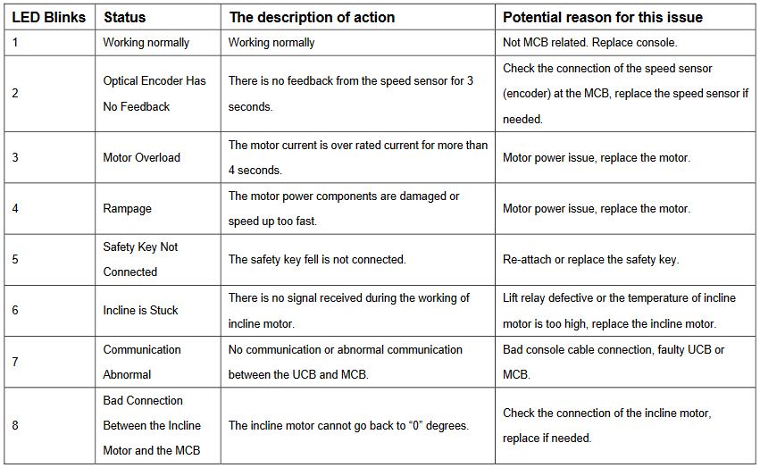
Edit 10/25/21: Here are the codes blinked out by the control board:
And here is a simple arduino sketch. You can probably ignore the 7-segment and rotary encoder parts, but it is successfully controlling the motor drive through a MAX485 chip on a breakout board.
/*
 * Encoder on A2, A3
 * Button on A1
 * MAX 485: 5v to DE, D8 to DI.  A and B to A and B of the treadmill controller
 * TM1637 display clock on 2, data on 3
 * Short out the middle "safety key" pins
 * Take power from one of the treadmill controller pins (which one?)
 * Treadmill header has 8 pins (left to right, latch at the bottom):
 * 1 - 12v
 * 2 - 12v
 * 3 - A or B?
 * 4 - Safety switch
 * 5 - Safety switch
 * 6 - A or B?
 * 7 - Ground
 * 8 - Ground
*/


#include <AltSoftSerial.h>
//https://www.pjrc.com/teensy/td_libs_AltSoftSerial.html

#include <SimpleTimer.h>
//https://github.com/jfturcot/SimpleTimer

#include <RotaryEncoder.h>
//http://www.mathertel.de/Arduino/RotaryEncoderLibrary.aspx
//https://github.com/mathertel/RotaryEncoder

#include "OneButton.h"
//https://github.com/mathertel/OneButton

#include <TM1637Display.h>
//https://github.com/avishorp/TM1637

#include <EEPROMex.h>
//https://github.com/thijse/Arduino-EEPROMEx

const int encoderButton = A1;
const int encoderA = A2;
const int encoderB = A3;
const int dispClock = 2; //D2
const int dispData = 3; //D3


AltSoftSerial ss;
SimpleTimer timer;
OneButton encoderButt(encoderButton, true);
RotaryEncoder encoder(A2, A3);
TM1637Display display1(dispClock, dispData);

bool halt = true;
int setSpeed = 0;
int curSpeed = 0; //ramp this up until it reaches the set speed
int savedSpeed = 0;
const int speedCount = 123;

const byte b1[] = {0,0,0,0,1,1,1,1,1,1,1,1,2,2,2,2,2,2,2,3,3,3,3,3,3,3,3,4,4,4,4,4,4,4,5,5,5,5,5,5,5,5,6,6,6,6,6,6,6,7,7,7,7,7,7,7,7,8,8,8,8,8,8,8,9,9,9,9,9,9,9,9,10,10,10,10,10,10,10,11,11,11,11,11,11,11,12,12,12,12,12,12,12,12,13,13,13,13,13,13,13,14,14,14,14,14,14,14,14,15,15,15,15,15,15,15,16,16,16,16,16,16,16,16};
const byte b2[] = {0,161,195,230,8,42,76,111,145,179,213,248,26,60,94,129,163,197,231,10,44,78,112,147,181,215,249,28,62,96,130,165,199,233,11,46,80,114,148,183,217,251,29,64,98,132,166,200,235,13,47,81,116,150,184,218,253,31,65,99,134,164,202,236,15,49,83,117,152,186,220,254,33,67,101,135,170,204,238,16,51,85,119,153,188,222,0,34,101,103,137,171,206,240,18,52,87,121,155,173,224,2,36,70,105,139,173,207,242,20,54,88,123,157,191,225,4,20,54,88,123,157,191,225};
const byte b3[] = {221,16,201,186,144,116,105,188,33,197,216,18,156,188,101,79,171,182,82,43,11,210,8,154,186,99,250,96,132,229,70,87,142,23,64,51,212,48,87,130,38,194,136,186,94,57,221,121,172,63,219,60,79,236,117,172,189,135,230,2,54,175,118,86,112,234,51,19,158,122,103,131,132,93,125,222,20,9,237,132,81,76,168,118,5,220,105,141,161,69,139,127,49,235,188,156,116,237,78,110,92,210,242,43,131,32,0,217,80,195,39,131,86,49,213,180,119,195,39,131,86,49,213,180};
const int sfm[] = {0,262,314,366,418,471,523,575,628,680,732,785,837,889,941,994,1046,1098,1151,1203,1255,1308,1360,1412,1464,1517,1569,1621,1674,1726,1778,1831,1883,1935,1987,2040,2092,2144,2197,2249,2301,2355,2406,2458,2510,2563,2615,2667,2721,2772,2824,2878,2929,2981,3033,3087,3138,3190,3244,3295,3347,3401,3453,3504,3556,3610,3661,3713,3767,3818,3870,3924,3976,4027,4079,4133,4184,4236,4290,4342,4393,4447,4499,4550,4602,4656,4708,4759,4813,4865,4916,4970,5022,5074,5125,5179,5231,5282,5336,5388,5440,5493,5545,5597,5648,5702,5754,5805,5859,5911,5963,6016,6068,6120,6171,6225,6277,6329,6382,6434,6486,6539,6591,6643};

//eeprom memory locations
const int memAddress = 20;
const int memBase = 350;


void setup() {
  //interrupts for encoder
  PCICR |= (1 << PCIE1);    // This enables Pin Change Interrupt 1 that covers the Analog input pins or Port C.
  PCMSK1 |= (1 << PCINT10) | (1 << PCINT11);  // This enables the interrupt for pin 2 and 3 of Port C.
  //Serial.begin(9600);
  ss.begin(9600);
  timer.setInterval(100, sendSpeedPacket);
  encoderButt.attachClick(startStop);

  // Set Up EEPROM
  EEPROM.setMemPool(memBase, EEPROMSizeNano);

  //Load the stored speed value
  setSpeed = EEPROM.readInt(memAddress);

  display1.setBrightness(2);
  updateDisplay();
}

void loop() {
  // put your main code here, to run repeatedly:
  timer.run();
  encoderButt.tick();
  readEncoder();
  updateDisplay();
}

void sendSpeedPacket() {

  if(halt == true) { //send the stop packet
    ss.write((byte)0);
    ss.write((byte)255);
    ss.write((byte)241);
    ss.write((byte)2);
    ss.write((byte)0);
    ss.write((byte)0);
    ss.write((byte)221);
  }
  else { //send the current speed packet
    ss.write((byte)0);
    ss.write((byte)255);
    ss.write((byte)241);
    ss.write((byte)2);
    ss.write((byte)b1[curSpeed]);
    ss.write((byte)b2[curSpeed]);
    ss.write((byte)b3[curSpeed]);
  }

  if (halt == true){
    curSpeed = 0;
  }

  if (curSpeed < setSpeed && halt == false) { //this ramps the sent speed up until it hits the set speed
    curSpeed++;
  }
  if (curSpeed > setSpeed && halt == false) { //this immediately reduces the sent speed to the set speed
    curSpeed = setSpeed;
  }

  //Serial.print(halt);
  //Serial.print(" ");
  //Serial.println(curSpeed);

}

void startStop () {
  halt = !halt;
  EEPROM.writeInt(memAddress, setSpeed); //save the speed every time the button is pushed... so that on next power up it is not zero
}

void readEncoder() {
  static int pos = 0;

  int newPos = encoder.getPosition();
      if (pos > newPos) {
        setSpeed = setSpeed - 1;
      }
      else if (pos < newPos) {
        setSpeed = setSpeed + 1;
      }
      pos = newPos; //--keep

      setSpeed = constrain(setSpeed, 0, speedCount);


}

ISR(PCINT1_vect) {
  encoder.tick(); // just call tick() to check the state.
}


void updateDisplay() {
  display1.showNumberDecEx(sfm[setSpeed], 0, true);  //Set time should always show on display 1
//  Serial.print("Minutes: ");
//  Serial.print(seconds / 60);
//  Serial.print("Seconds: ");
//  Serial.println(seconds & 60);
}
Update 11/2022 – here’s a list of some of the unique commands I saw. I didn’t test or try to capture the incline setting, but if we’re lucky maybe it’s in here:
These are the unique commands and responses I recorded just after powering up:
Source	Unique Message		Count	Comment
Panel	0 255 14 0 14			1
Motor	128 0 14 0 5			1
Panel	0 255 9 64 0 95 241		2
Motor	128 0 9 0 107			2
Panel	0 255 159 0 9			30	Common while idle and running
Motor	128 0 159 64 0 0 160	30	Probably reply to 0 255 159 09
Panel	0 255 143 64 0 0 187	81	Speed command? 143
Motor	128 0 143 0 238			81


And here are the unique commands while it was running at a steady .5 mph:
Source	Message						Count	Comment
Panel	0 255 143 64 0 133 8		77	Speed command? 143
Motor	128 48 143 0 48				77	Same acknowledgement to speed command as 1 mph
Panel	0 255 111 64 0 20 14		76	Same while running at 1 mph
Motor	128 48 111 0 69				76	same response as running at 1 mph
Panel	0 255 159 0 9				23	Common while idle or running
Motor	128 48 159 64 0 37 56		11
Motor	128 48 159 64 0 165 180		10