Part 2 for the lathe power feed. I’ll make at least one more to go over the wiring and controls.
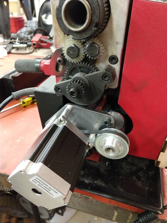
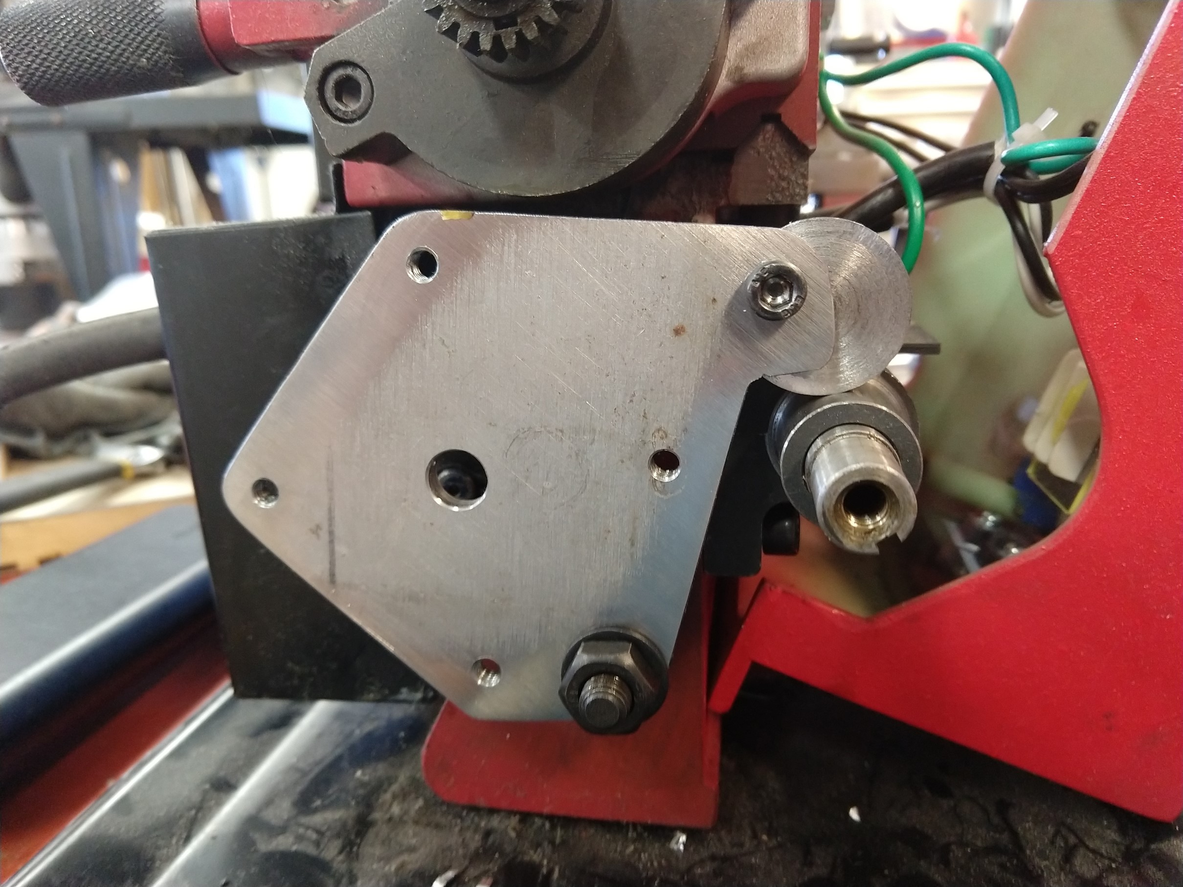
This mount puts the motor on the left side of the lathe and replaces the original banjo for the changegears. This is the easiest/cheapest way I could come up with to attach the motor to the leadscrew. Originally I intended to extend the leadscrew and drive it from the tail end, but that is a bit more challenging and I thought this would be easier for the home-shop. The motor will interfere with the cover, so you may need to cut a hole in it or leave it off. I put some thought into this so that it could be made with basic tools (no slots, welding, etc).
Bill of Materials
| Quantity | Description |
| 1 | Steel or aluminum plate 4″ x 5″ (or larger). 3/16″ or 1/4″ thick |
| 4 | M5 x .8 Screw – 35mm long |
| 1 | M5 x .8 Screw – 15mm long |
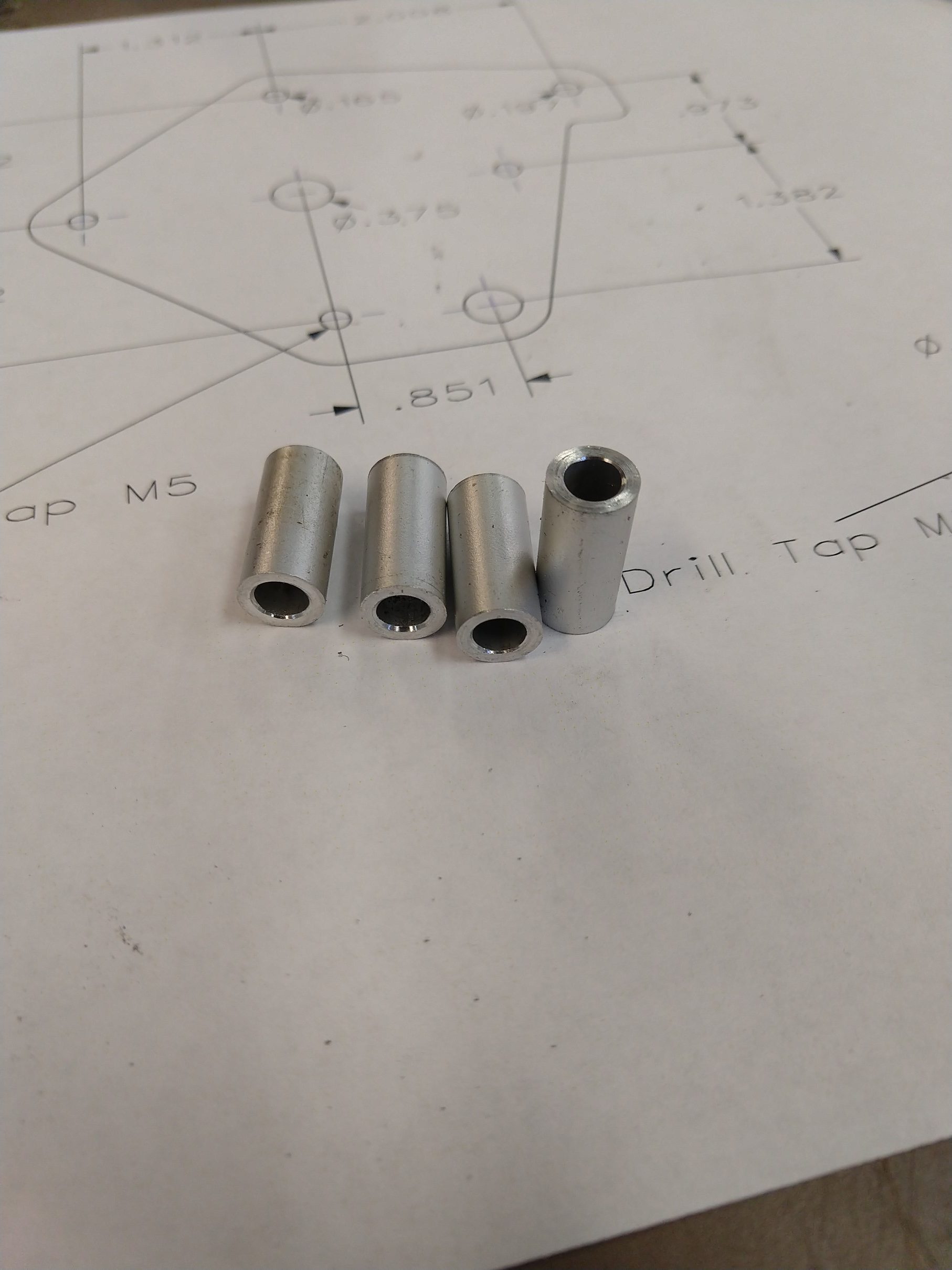
| 4 | Spacer 5mm ID – .700″ long (see drawing) (make from round stock) |
| 1 | NEMA 23 Stepper (notes below) |
| 1 | GT2 pulley – 60 tooth 12mm bore |
| 1 | GT2 pulley – 20 tooth (bore to match stepper shaft) |
| 1 | GT2 belt – 200 tooth, 6mm wide |
Tools required
- M5 x .8 tap
- 4.2mm or #19 drill for M5
- 8mm or O drill (.3160″)
- 5mm or #7 or #8 drill
- Tools for cutting the plate
- Hacksaw and a drill is the basic requirement
- Bandsaw, scroll saw, mill, CNC, LASER… these are optional. Use whatever you want
- File or sandpaper
- Lathe (for making spacers)
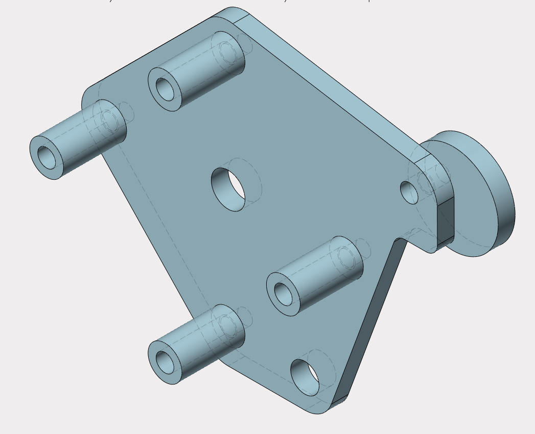
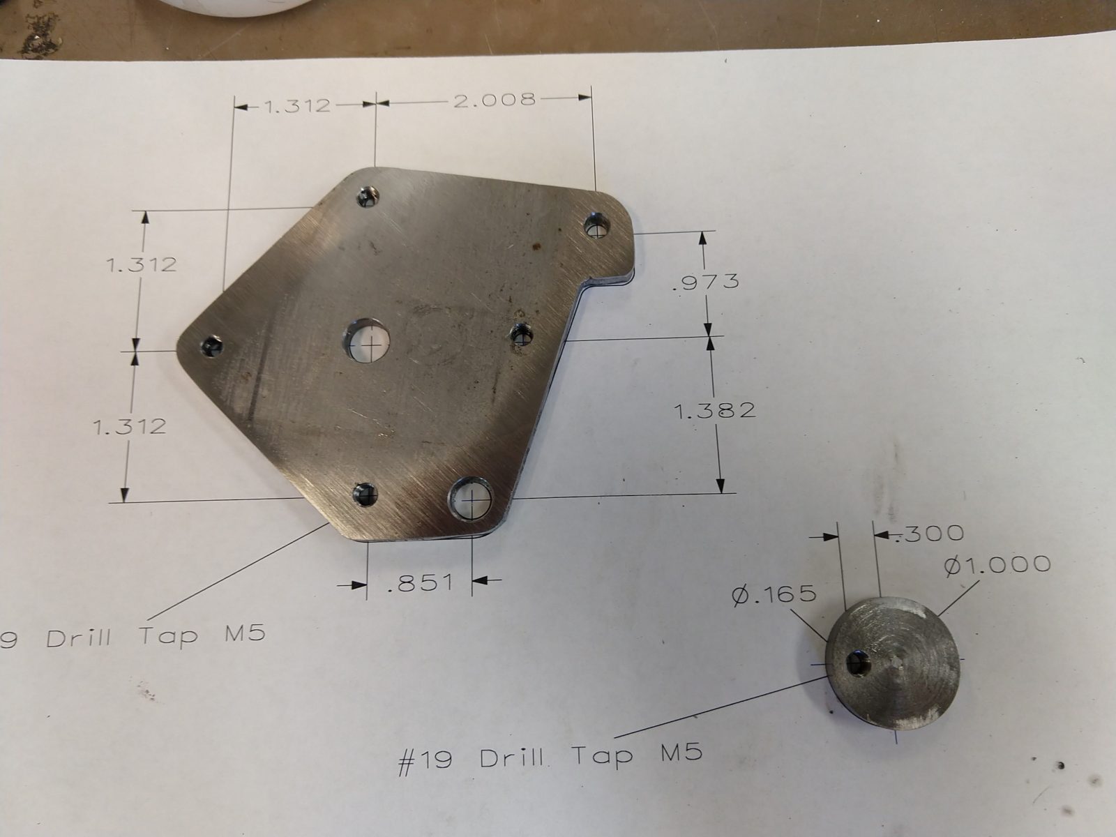
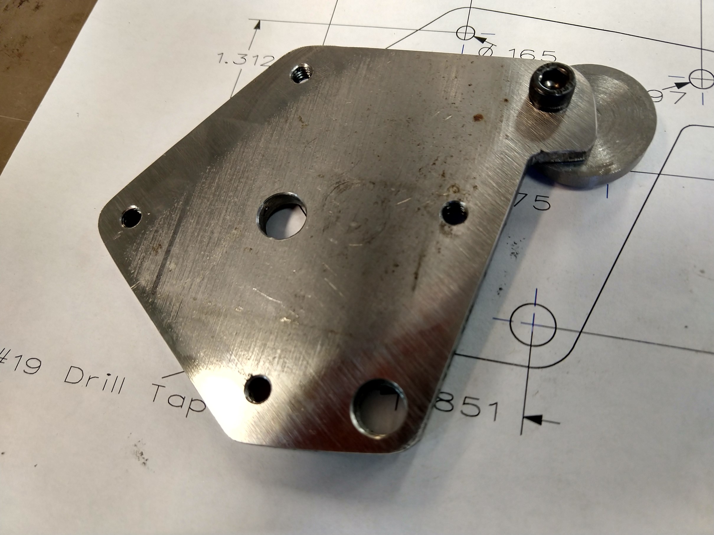
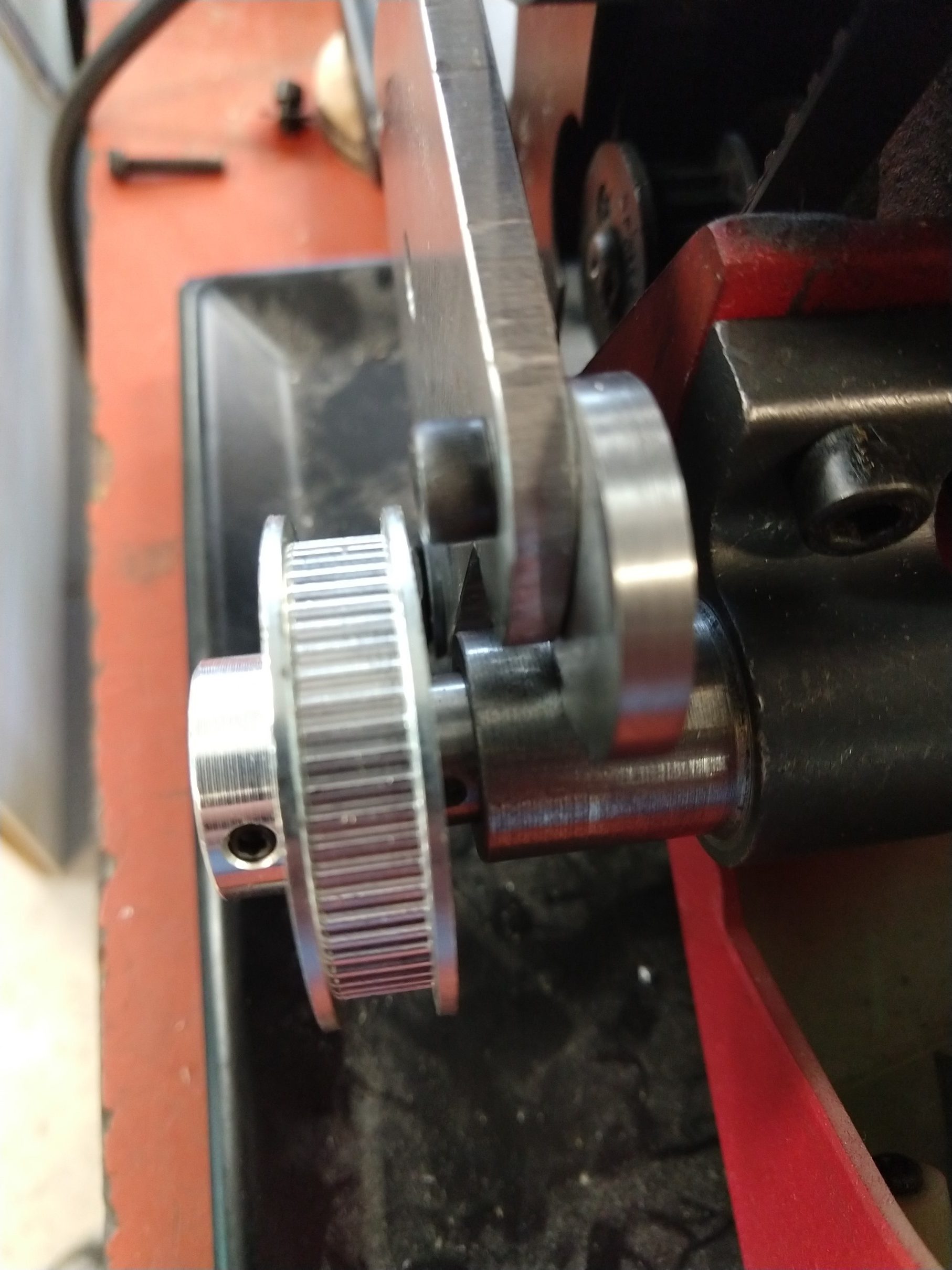
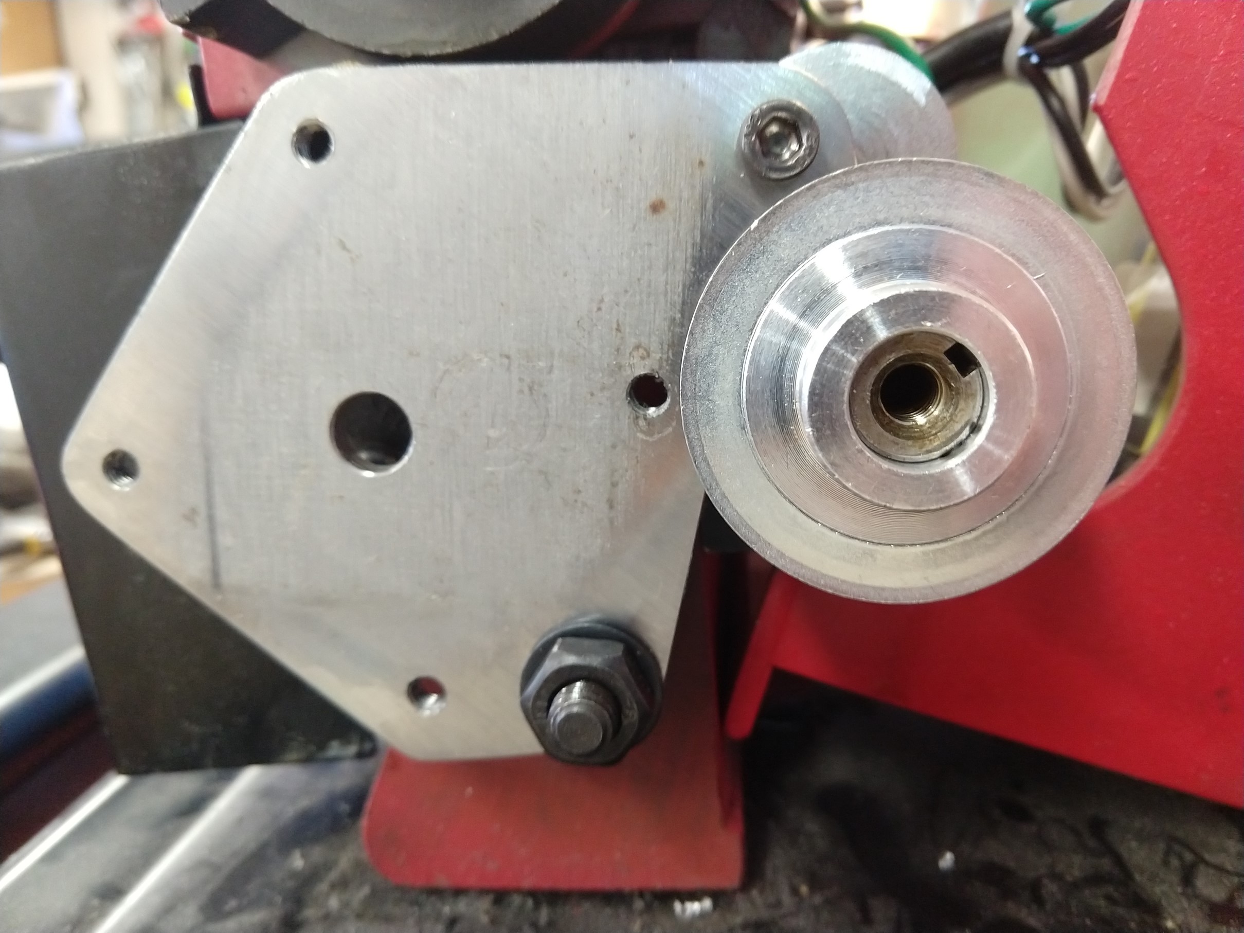
The only critical dimensions on this part are the four tapped M5 holes for mounting the motor. It is also important that the four spacers be the same length so the motor is square to the plate. Other than that, the outside contour of the part only needs to clear any obstructions. The circular part with the offset hole is used to adjust the belt tension, it rotates and presses against the leadscrew bushing/bearing – if that doesn’t make sense it should be more clear in the photo. The OD of the spacers is only important for the one that is closest to the leadscrew pulley, it may be necessary to relieve this for clearance.
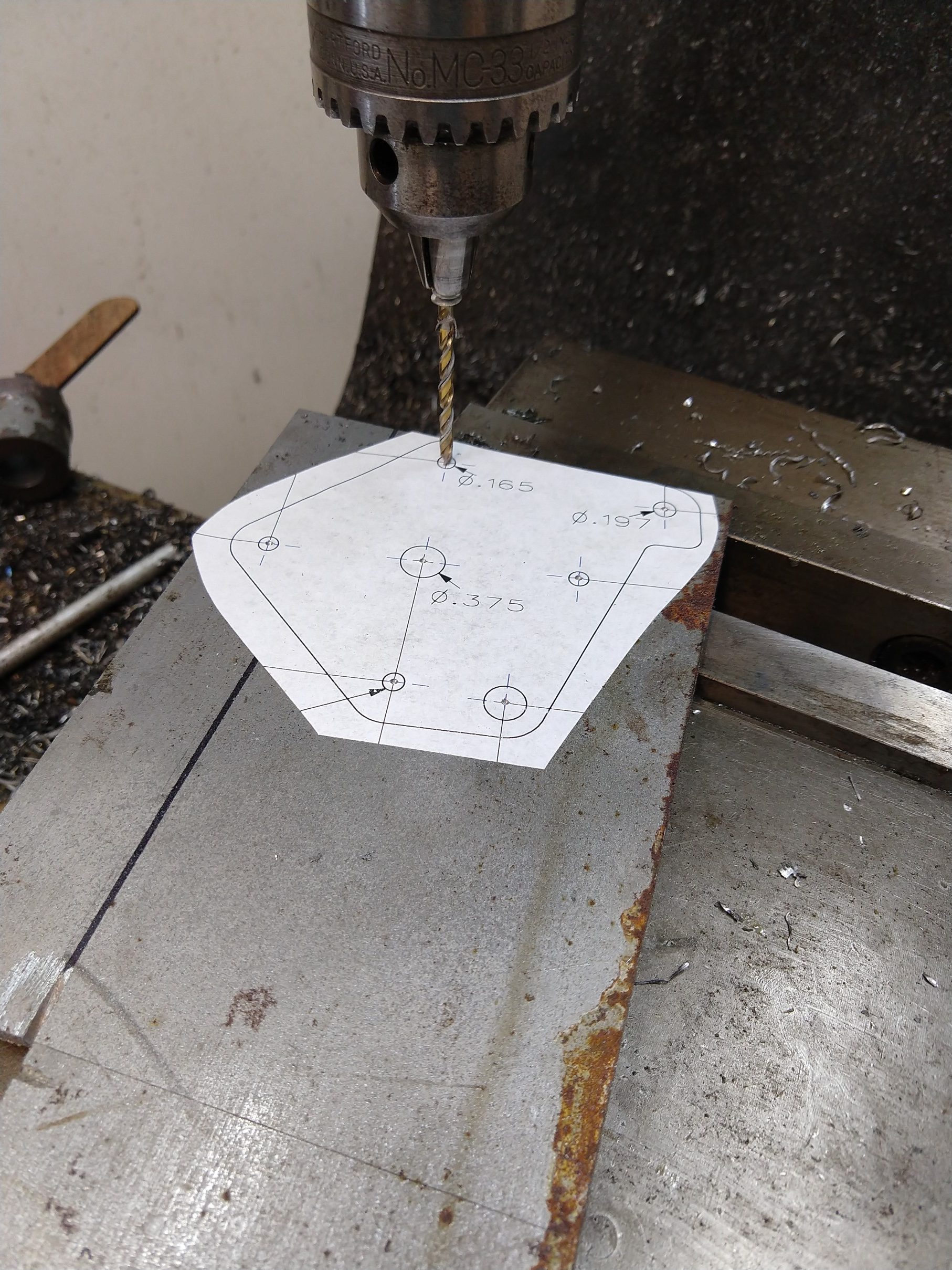
I recommend printing the drawing out at 1:1 scale and gluing it to your plate, center punch the hole locations for drilling and use a saw and files to get the right outside shape.
Hopefully it is clear how this mounts up to the lathe in the photos. Take off all of the change gears including the key on the leadscrew and set them aside (or probably lose them forever, which is what I will probably do). The banjo also needs to be removed, but the nut and washer will be reused. Don’t tighten the set screws on the pulleys until you have the motor mounted, this way you can shift them around for alignment. Remember to put the belt on!
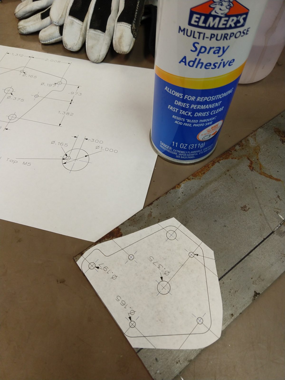
Use drawing as a template 
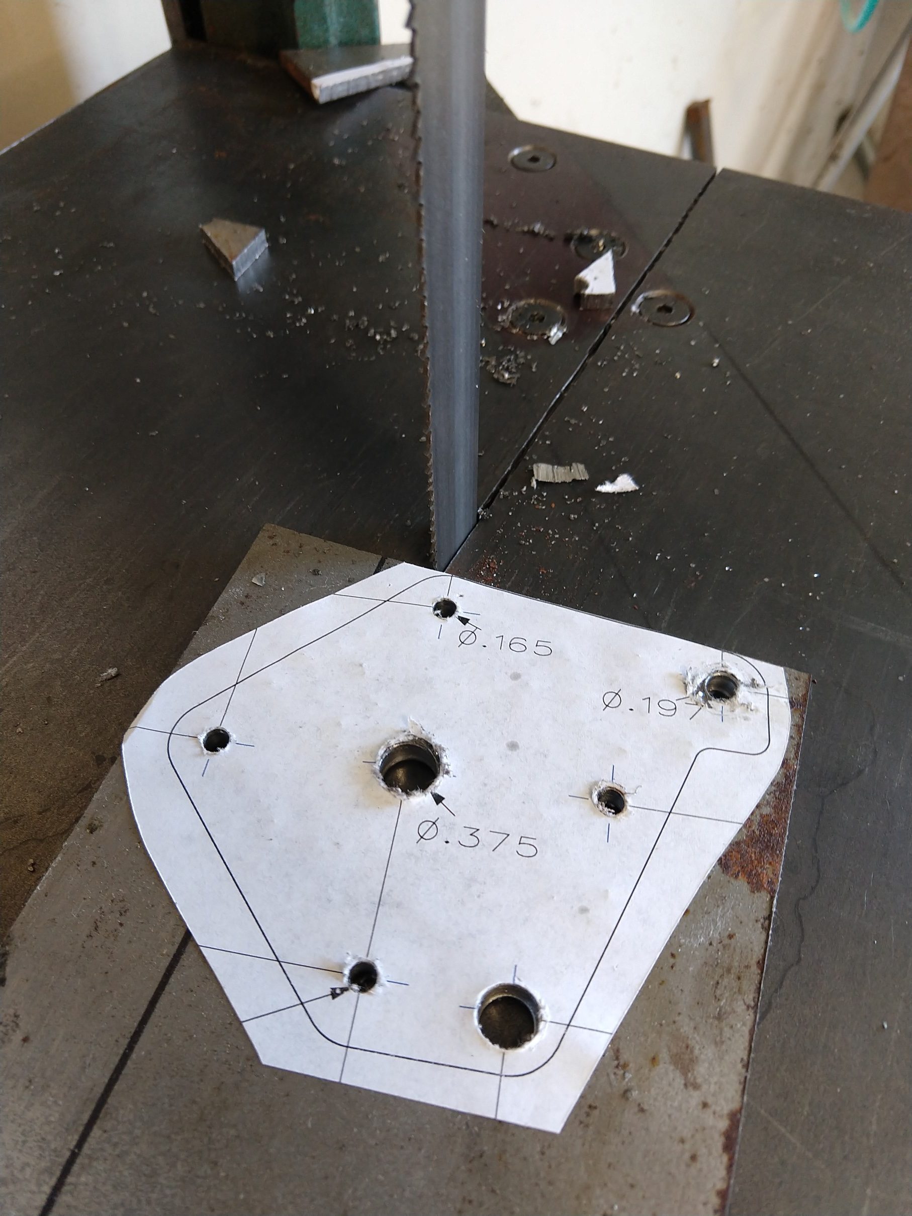
Center punch and drill 
Cut outline 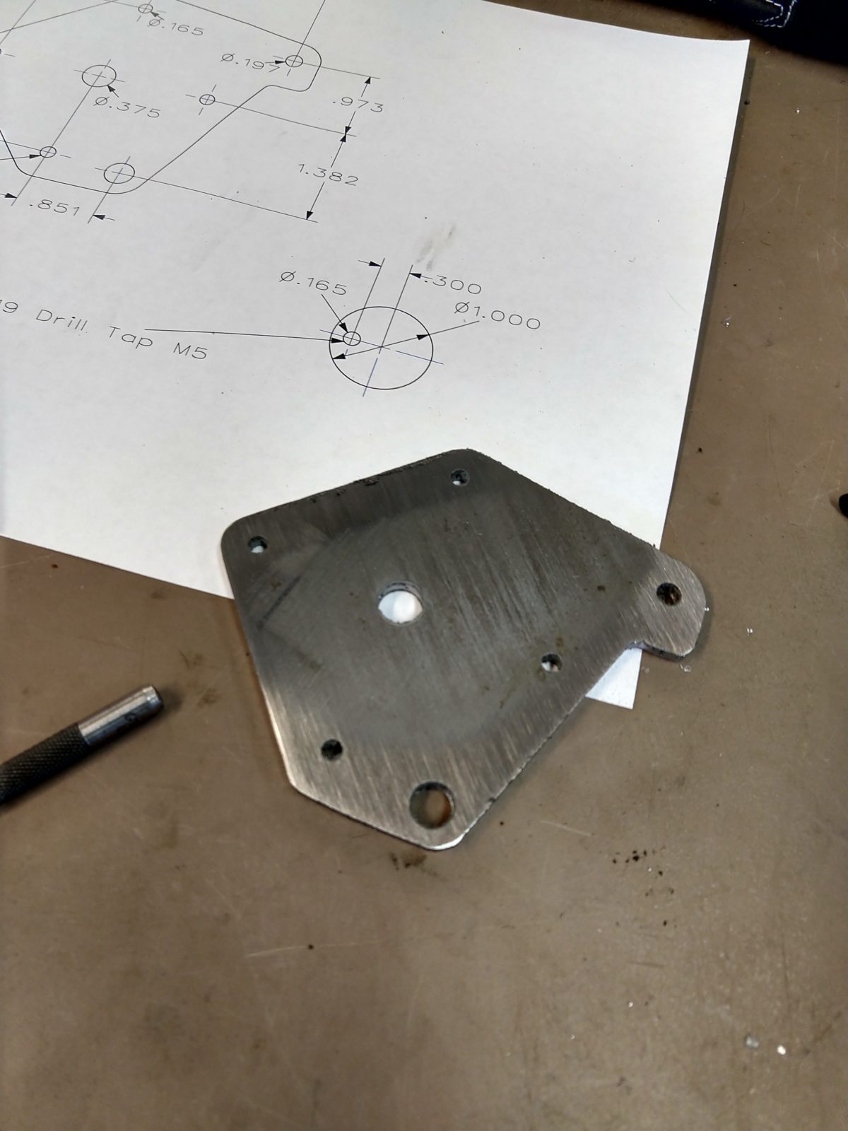

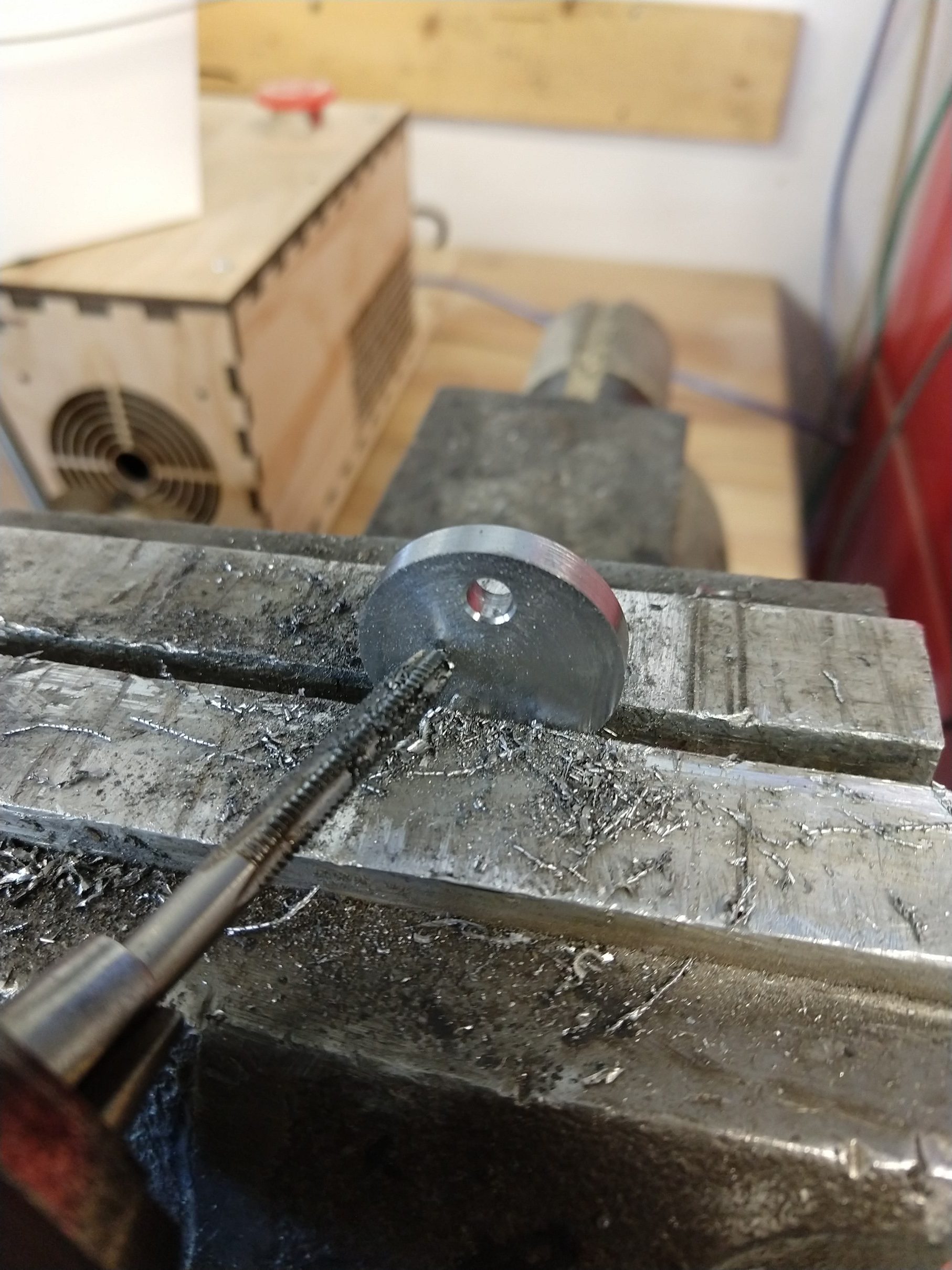
Tap 5mm holes 
Assembled 
Replaces the banjo 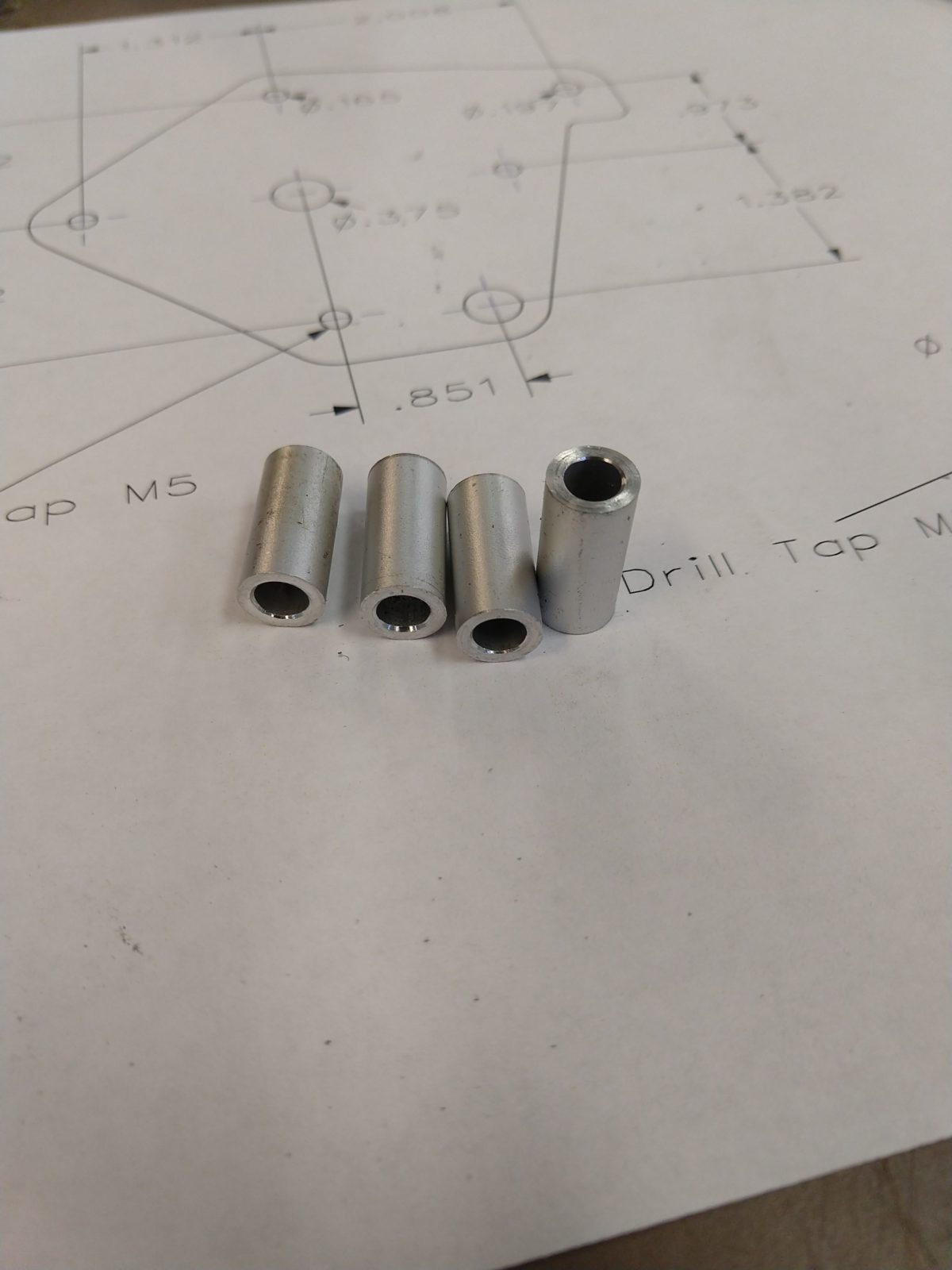
Spacers 


Regarding the motor – I chose a 1.9 nm stepper. I have not tested this thoroughly yet, but so far I have this running at 2 amps and it doesn’t seem to have any trouble moving the carriage while cutting in aluminum. I think a smaller motor will probably be sufficient – but I don’t know the limits yet.
That’s it! I’ll follow up with the details for the control in another post.
hey Elliot,
thank you for sharing this and the arudino code! just finished the parts.
Have you ever expanded this beyond speed and direction? like auto stop etc? i think i saw you had something like that in your tests. why did you not implement it?
take care and keep on making