I just became the surprise owner of this vacuum forming machine:
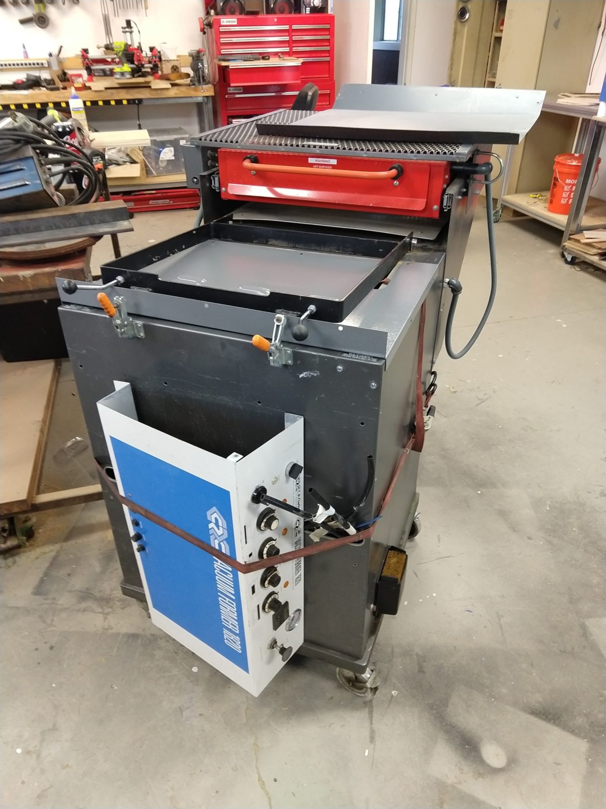
This is a C. R. Clarke Vacuum Former 1820. Looks like this model is still made currently (link to site), but I would guess that this one was made in the mid ’90s. The concept is fairly straightforward: a form/mold is placed on a moving platform inside, material is clamped in place over it, the heater slides forward to heat it, then the mold is raised and vacuum applied. This one has a few things wrong with it:
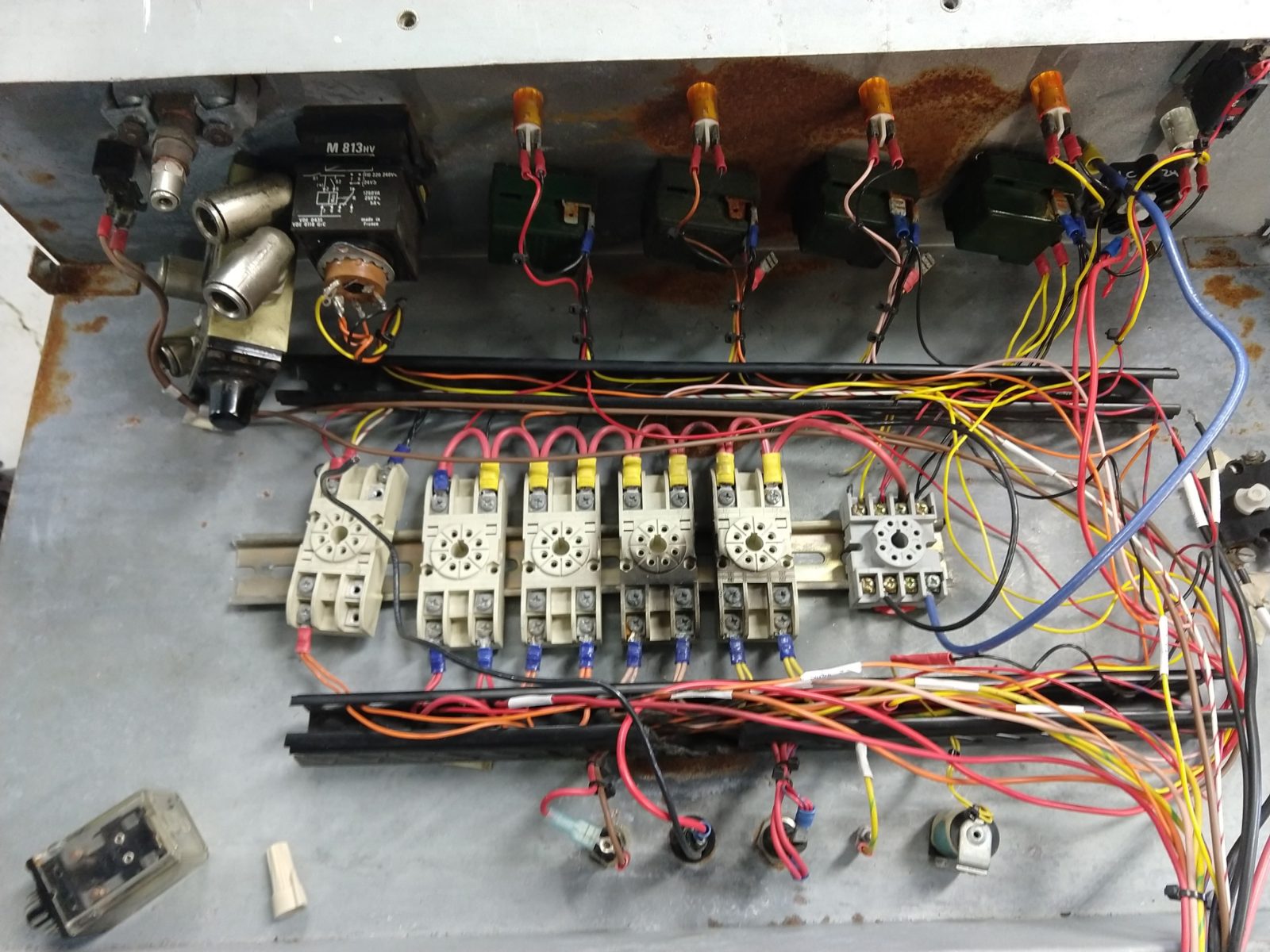
- Control panel has been partially removed
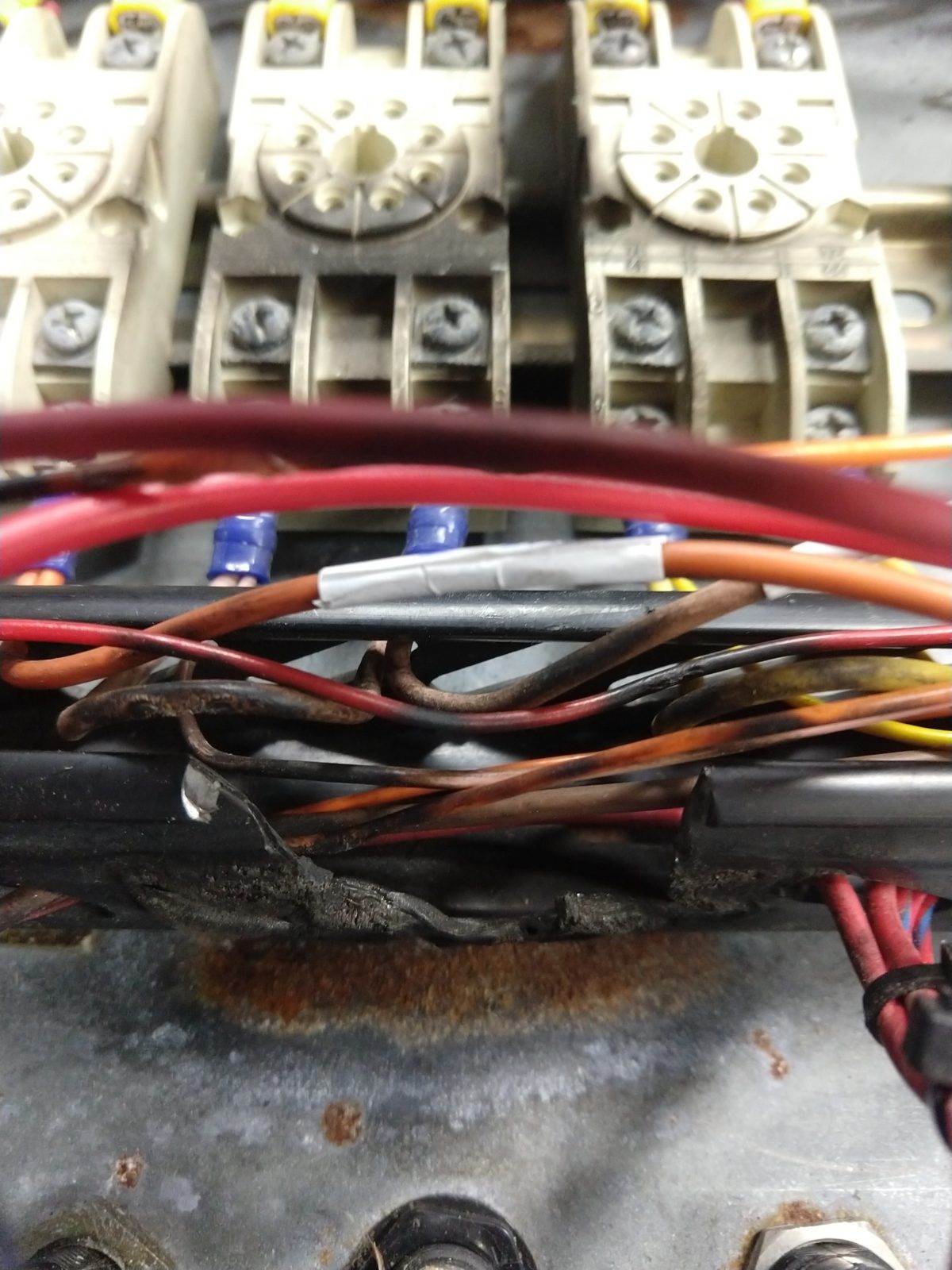
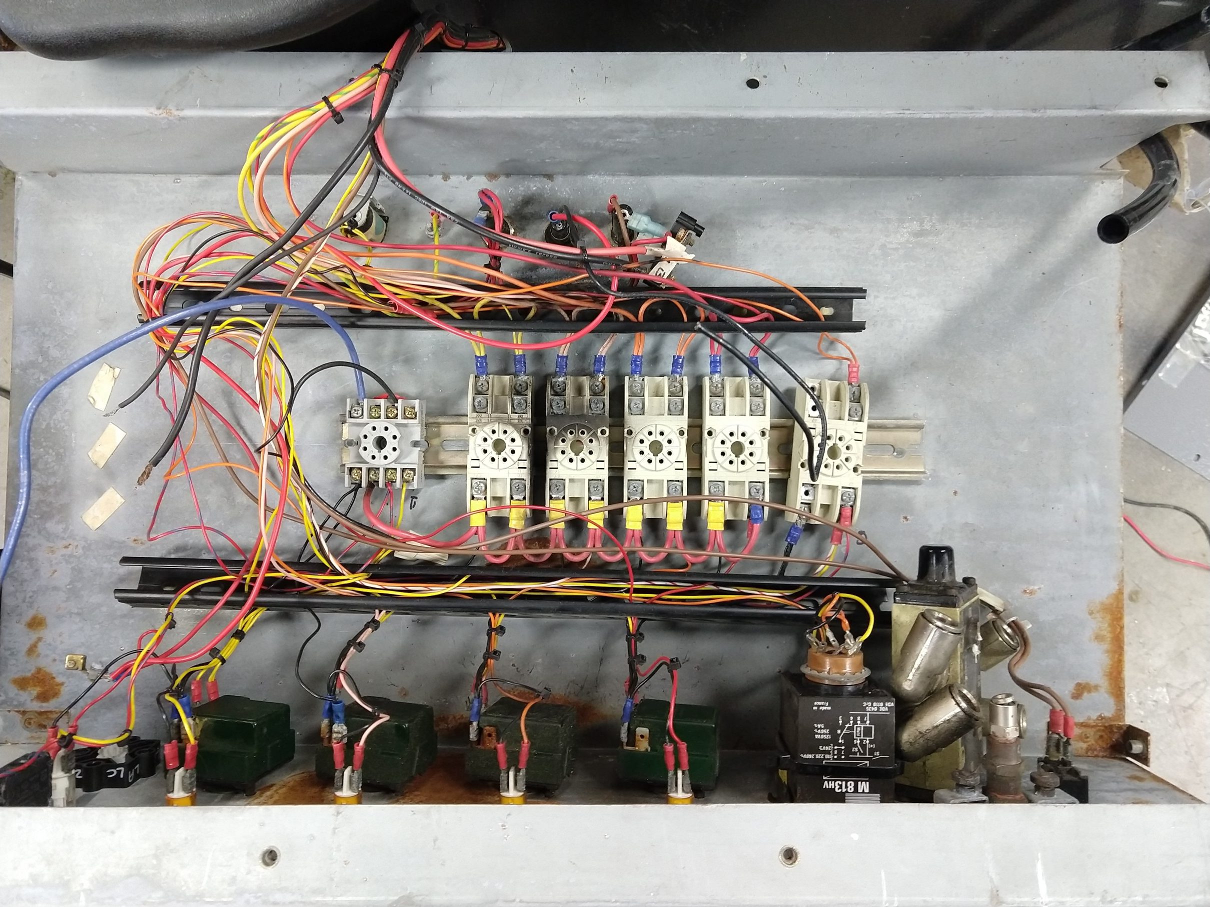
- Something electrical caught fire or let out some smoke
- Power switch broken/disassembled and there are many wires disconnected (and a suspicious wire nut, always a bad sign)
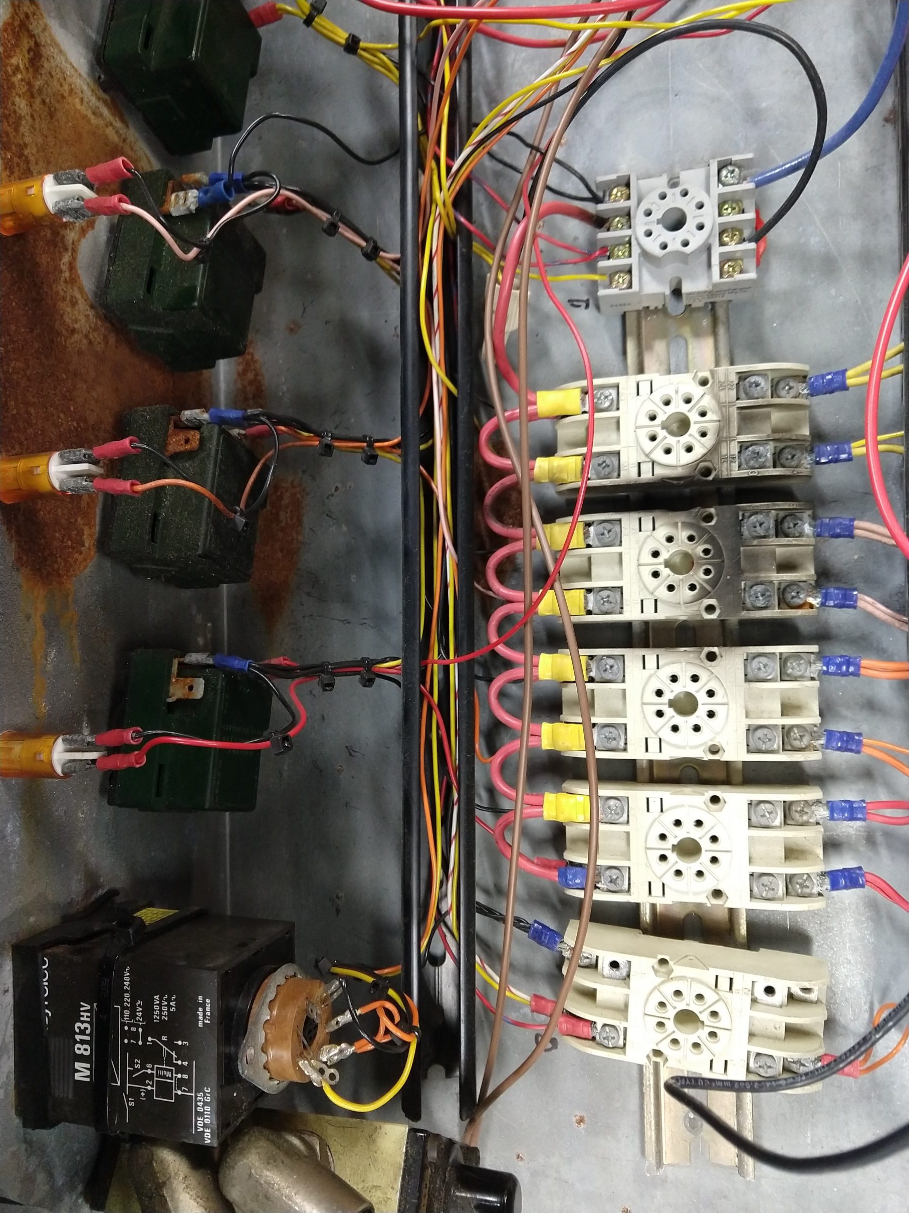
- One of the relay bases is broken from it’s rail, another relay is melted, and many of the relay contacts look worn
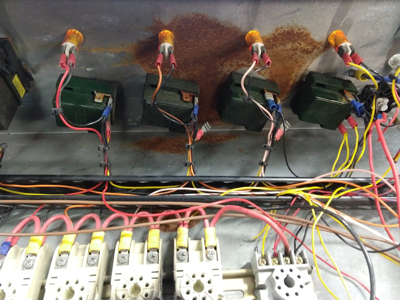
- One of the heat controllers is cracked open, all are rusted
- Corrosion on all of the connectors. It probably spent some time outside
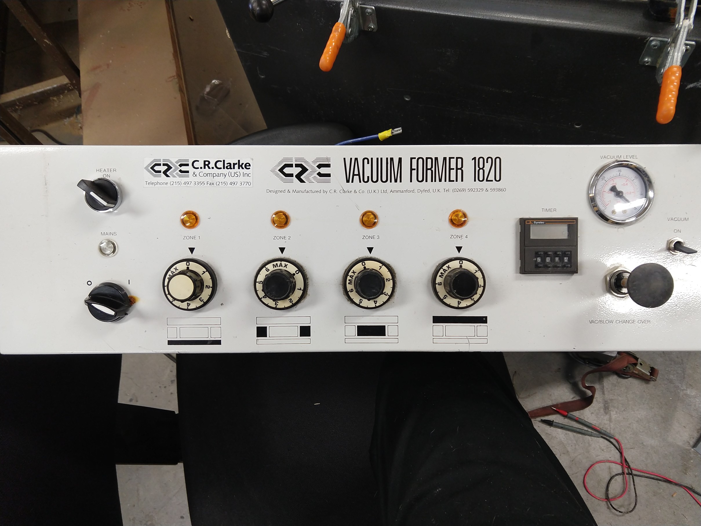
The controls are completely electromechanical except for the timer, which has exactly two transistors in it, and everything in the panel including the indicator lights runs at 220 volts. The heating elements and vacuum system look like they’re in good shape, so I would say it’s worth fixing. With that said… the amount of corrosion on everything in the panel and the obvious burn marks from a previous fire give me doubts about just hooking everything back up. Because of the high voltage, I would want to replace all of the heater controls, timer, connectors, and relays… and the original stuff isn’t super easy to come by. I plan to replace it all, but first I have to understand how it was supposed to work.
Ignoring the vacuum part, there are only a couple things that actually have to happen: the heat level needs to be regulated, and a timer needs to tell the operator how long to keep the heat over the material. Heat regulation appears to be open loop with a sort of thermostat – Diamond H 30ER1HT 38. From what I gather these are also referred to as a “simmerstat” and are used on some kinds of hot plates/kitchen/catering type appliances. Instead of sensing the temperature of air like a thermostat, there is an internal heater acting on the bimetallic strip that opens and closes the contacts. When the knob is off the contacts are open, when it is at MAX they are closed, and in between it cycles open and closed. Basically this is PWM with variable duty cycle, but with a very slow frequency.
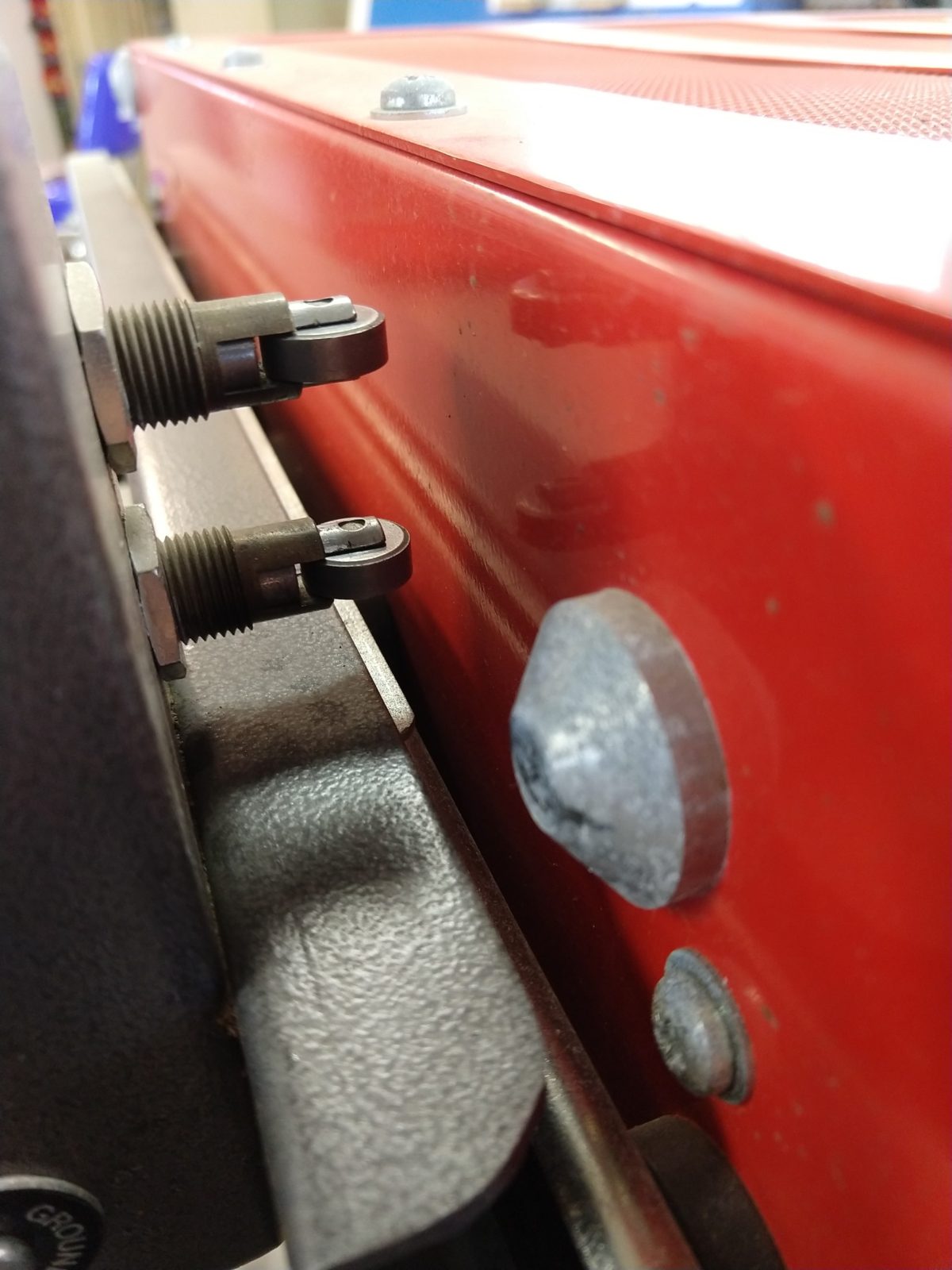
As for the timer, there are two contacts (pictured above) on the heater. When the heater slides out the lower contact starts the timer when the drawer slides are fully extended, and when it is returned home the upper contact resets the timer (also cancels the buzzer that is sounded when it hits zero). The placement of the bumps on the heater are clever and probably helps prevent people from leaving the heater in some intermediate position where it interferes with other things.
The plan:
- Replace all of the relay/timer logic with a microcontroller
- Heater controls will be replaced with potentiometers
- Extremely slow PWM to relays for heaters
- Timer display and control
- Buzzer will be kept but activated with a relay
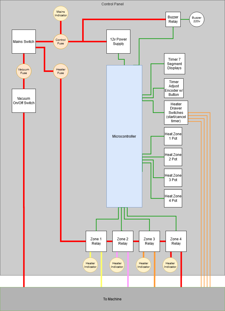
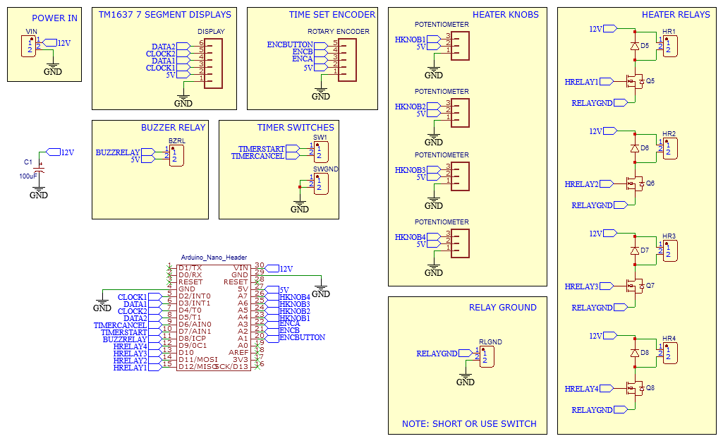
I will have to add a DC power supply for this to work, but a big benefit of that is that I can test everything out on the bench, far, far away from 220v mains. AC won’t be involved anywhere in this circuit, it will only be switched by relays:
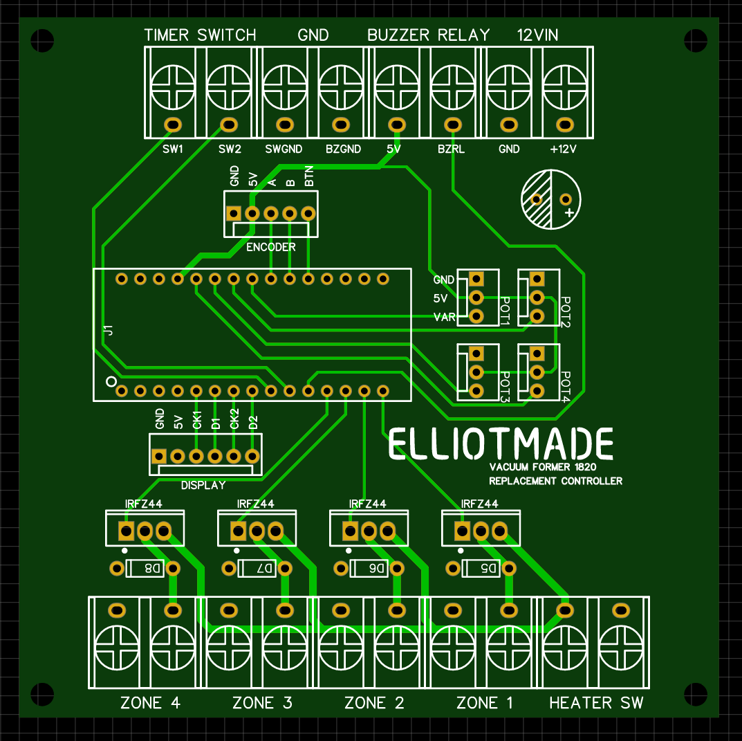
I didn’t bother prototyping this – just went ahead and ordered from JLCPCB so I will find out what mistakes I made in a few days when it gets here. The components I chose are based on what I have on hand, not that there are many of them, it’s mostly connectors. I don’t think four knobs for the heaters are really necessary, but I wanted to keep the panel the same if possible. I used potentiometers for these because I don’t have a handy way to interface five rotary encoders with an arduino nano.
Here are some more photos for future-me to reference, and I’ll post again when I make more progress!


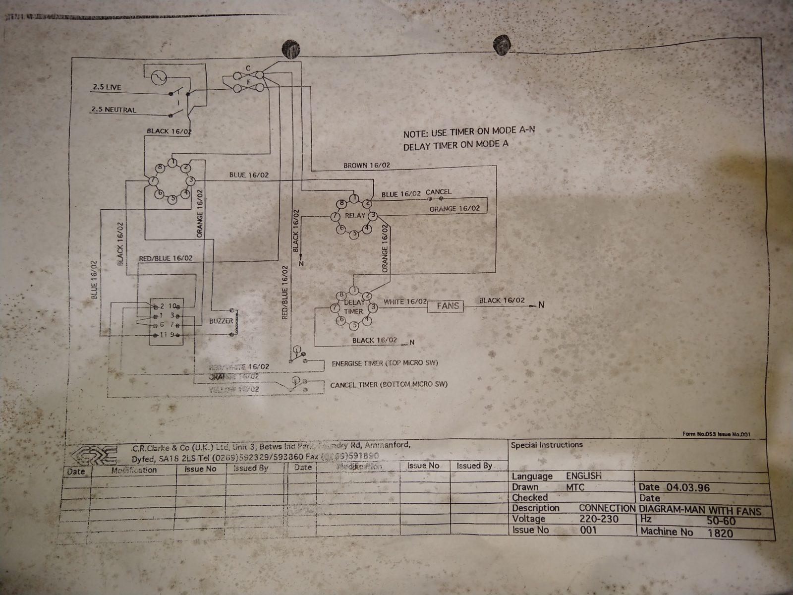
This came with it… but it didn’t help me 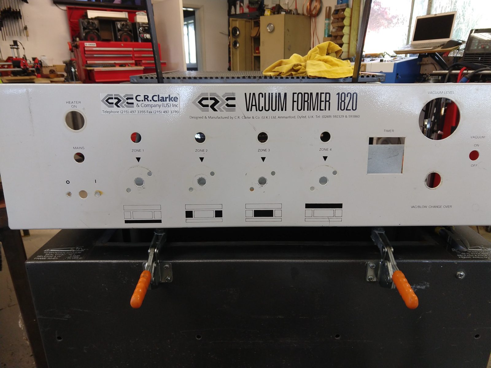


Hello
Do you have a link for the pcb files ?
Thanks a lot
Br
David
Added them to this post and here you go: https://elliotmade.com/wp-content/uploads/2020/05/vacuumformerpcb.zip
The JSON file is for easyEDA and there should be gerbers in there as well.