bookmark_borderDead Raspberry Pi Pico – or is it?

I’ve been having some fun with the Raspberry Pi Pico and Circuitpython thanks to Mark Hughes and the Teach Me PCB course that he’s putting on at the moment. For whatever reason, I decided it would be cool to iterate on my word clock design. I’m not done yet, but I am making sure to struggle along the way. Here’s a problem I had with the Pico I wanted to share in case someone else does what I did:

TLDR: Don’t pull some? pins high without first configuring them as input or output in your code. Go to fix

This is what I did:

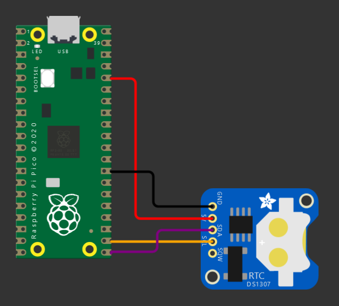
Wire the clock up – 3v to VCC, GND to GND, GP16 to SDA, GP17 to SCL (just like this guy did).

Something like this

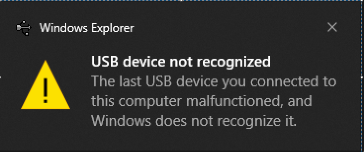
Power it back up – immediately windows says there is something wrong with my device.

Symptoms:

  • Windows makes a sad dingle noise and says there is something wrong with the device
  • Device manager shows a device with “device descriptor request failed”
  • Replacing the driver doesn’t help
  • Same problem if you plug the Pico into another computer
  • Your code doesn’t run
  • No serial port (naturally, USB isn’t working)
  • Power up with the BOOTSEL button held down does work, and allows loading UF2 files
  • Re-loading a circuitpython or micropython UF2 doesn’t change the behavior
  • Undoing the wiring doesn’t make the problem go away
  • Flashing the Pico with the Arduino framework and using C++ still works

It was a struggle to troubleshoot (I bricked 4 Picos before I found out how to recover them), although I admit I didn’t read the entire datasheet before embarking on this quest. I narrowed in on the cause by removing variables until I had only the RTC and Pico connected directly with wires. I found:

  • With only GND and VCC connected, there are no issues
  • If you plug the SCL and SDA in while the Pico is running, it is not interrupted, no problem
  • If you boot the Pico with SCL and SDA connected, all the bad things happen
  • Note at this point I have not added any code to configure GP16 and GP17, I am assembling the circuit first

What is the cause?

I noticed that the DS3231 module I’m using pulls SCL and SDA high when it is powered, this seems to be a key part of my problem. Initially I thought the flash was somehow being corrupted, but after making lots of guesses with help from the folks on the TMPCB Discord, on a hunch I tried setting my pins as inputs and bingo, no more problems. This could be correct, or could be a red herring, more important is how to recover.

What I think is happening is that during boot, if you leave these pins undefined and pull them high, it interrupts things after your code has started running but before the USB is initialized. In this state you don’t have a USB disk to update the code with, nor a serial port to figure out what’s up. Even switching to bootloader mode and replacing the Circuitpython UF2 file doesn’t help. It’s possible that this is a code-only problem, but it suspicious that it was reproducible by connecting the GPIOs.

I think this page and the note on line 28 here explain a similar problem, but I am using different pins.

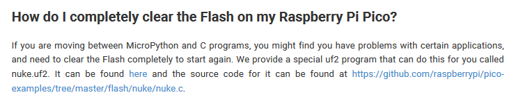
I found a reference to this “nuke” file in a forum post, here’s the description in the FAQ sheet and a link to the file:

Here’s what to do:

  1. Hope that you saved a copy of your code and libraries on your computer (you did, right?)
  2. Download the flash_nuke.uf2 file
  3. Connect the Pico to USB, hold the BOOTSEL switch while doing this to enter bootloader mode
  4. Copy the nuke file to the Pico drive
  5. Pico should reboot into bootloader mode again
  6. Copy the Circuitpython or Micropython or whatever UF2 to the Pico drive
  7. Pico should reboot in the usual mode now, copy your code and libraries
  8. Next time configure the pins before building and powering the circuit
Back in business

Thanks:

These links for clues:

https://nahog.medium.com/raspberry-pi-pico-dead-serial-5f57e622020f

https://forums.raspberrypi.com/viewtopic.php?t=314269

https://learn.adafruit.com/getting-started-with-raspberry-pi-pico-circuitpython/faq-and-troubleshooting

https://forums.adafruit.com/viewtopic.php?f=60&t=174992

https://github.com/adafruit/circuitpython/issues/4034

Wokwi for a screenshot

And to my pals from the TMPCB course for all the ideas.

bookmark_borderESP-32 Captive Portal

Purpose

As an amateur, I don’t know what I’m doing most of the time. When I set out to do this, all I knew was I wanted my device to automatically redirect users to a page after they connect to it’s wifi network, just like airports and hotels do. Turns out this is called a captive portal. I struggled for awhile to get this to work, so I’ll try to point out what does what in this example.

One (ab)use case for this is for projects that use a web page for configuration. Normally you need to navigate to that page with the IP address in a browser… which means you have to write it down somewhere, or print it on a display (if you have one), or my next best idea: print a QR code with a hyperlink to it. It is better if we can redirect the device right to the page we want without fussing around.

How it works… I think

Modern devices (windows, android, probably apple) and web browsers like to check to see if a newly connected WIFI network has internet access. They reach out to some known location, and if they get the right response, decide to stay connected and do their thing. Luckily there is a behavior on these devices designed to send you to a network sign-on page if it doesn’t get the reply it was hoping for, and that’s what this takes advantage of. Basically:

  1. When the device boots it has an IP address, default is 192.168.4.1 on the ESP32
  2. A DNS server is started, and it is configured to direct all traffic to that IP address
  3. We take advantage of the “not found” behavior of the web server and send whatever we want as a response to the original request
  4. The device thinks it’s going to network sign-on page – this is where we get to send it where we want – for example a configuration or remote control page for the device.
  5. Bingo, now it is easy to get to where you wanted in the first place, without having to type in the IP address

Hardware

An ESP32, nothing else. Easiest way is to use one of the dev boards available on amazon/ebay/whatever. It may be necessary to power it externally, as some modules have power issues over USB and may trigger the brownout detector when activating wifi. This is probably applicable to the ESP8266, or anything else using these libraries.

Libraries

I am using VS Code and Platform.io. Should also work with the Arduino IDE as long as you add the required libraries. Builtin libraries: wifi.h, dnsserver.h Other libraries:

Code

This is all available on Github here: https://github.com/elliotmade/ESP32-Captive-Portal-Example

/* ESP-32 Captive portal example
 * github.com/elliotmade/ESP32-Captive-Portal-Example
 * This isn't anything new, and doesn't do anything special
 * just an example I would have appreciated while I was searching for a solution
 */


#include <Arduino.h>
#include <AsyncTCP.h>
#include "ESPAsyncWebServer.h"
#include "DNSServer.h"


const char* ssid = "test_captive_portal"; //Name of the WIFI network hosted by the device
const char* password =  "";               //Password

AsyncWebServer server(80);                //This creates a web server, required in order to host a page for connected devices

DNSServer dnsServer;                      //This creates a DNS server, required for the captive portal


void webServerSetup(){
  
  //This is a super simple page that will be served up any time the root location is requested.  Get here intentionally by typing in the IP address.
  server.on("/", HTTP_GET, [](AsyncWebServerRequest *request){
    request->send(200, "text/html", "<!DOCTYPE html><html><head><title>Success</title></head><body><p>Hooray</p></body>");
    Serial.println("requested /");
  });


  //This is an example of triggering for a known location.  This one seems to be common for android devices
  server.on("/generate_204", HTTP_GET, [](AsyncWebServerRequest *request){
    request->send(200, "text/plain", "You were sent here by a captive portal after requesting generate_204");
    Serial.println("requested /generate_204");
  });

  //This is an example of a redirect type response.  onNotFound acts as a catch-all for any request not defined above
  server.onNotFound([](AsyncWebServerRequest *request){
    request->redirect("/");
    Serial.print("server.notfound triggered: ");
    Serial.println(request->url());       //This gives some insight into whatever was being requested
  });

  server.begin();                         //Starts the server process
  Serial.println("Web server started");
}


void setup() {
  
  Serial.begin(115200);

  WiFi.softAP(ssid, password);            //This starts the WIFI radio in access point mode
  Serial.println("Wifi initialized");

  Serial.println(WiFi.softAPIP());        //Print out the IP address on the serial port (this is where you should end up if the captive portal works)

  dnsServer.start(53, "*", WiFi.softAPIP());  //This starts the DNS server.  The "*" sends any request for port 53 straight to the IP address of the device

  webServerSetup();                       //Configures the behavior of the web server
  
  Serial.println("Setup complete");
}


void loop() {
  dnsServer.processNextRequest();         //Without this, the connected device will simply timeout trying to reach the internet
                                          //or it might fall back to mobile data if it has it
  
}

Notes

  • Works great with windows 10, you get to use your regular web browser
  • Android devices take you to the page, but it may be in the embedded web browser instead of your usual one

Apple

  • Haven’t figured out how to properly redirect IOS devices, but at least they (it – sample size of 1) are happy to stay connected
  • Some hours of googling haven’t revealed a great way to do this, there are scattered discussions around, but nothing amazing
  • I liked the “success is the key to success” note from this thread: https://www.esp8266.com/viewtopic.php?f=34&t=4398 so I went ahead and followed that advice. Need to test without it to see if it actually made a difference

Acknowledgements

Thanks to other humans that shared info about this already. I’m not doing anything new, but just trying to explain things in a way that makes sense to me…

bookmark_borderJohn Deere Rototiller

I thought I would be smart and save some money and get a used tiller for the garden. Instead what I did was buy some scrap metal, then spend more time and money to turn it back into a tiller. The guy that was selling it described it as a “bad bearing”; I bet he was laughing as soon as I left. Luckily it was cheap.

Photo from the listing

To be fair to the guy, it did have a bad bearing… in the exploded gearbox. It had clearly been apart, so no doubt he knew what was up.

How do you fix that? This is a 40-series from the ’70’s, most parts are unavailable, and even worse, the shaft connecting the chains on the ends to the gearbox in the center is one solid piece. In order to disassemble it I would have to press that shaft almost three feet through the box to get it out. My answer was to replace the whole thing with the cheapest gearbox from China I could find on Ebay and adapt it to work in it’s place.

Here’s what I did:

  • Cut the shafts to remove the old gearbox
  • Built up a mounting plate to hold it in place
  • Shortened the original shafts, turned them down, and machined a keyway so I could use standard shaft couplers
  • Used a mounted bearing and made a shaft adapter to connect to the PTO shaft
  • Cut down the original PTO shaft to a shorter length
  • Laser cut new gaskets for the chain cases

The result: it works! I spent about what it costs to rent one of these three times, so in my mind I need to get three day’s use out of this to break even. Long term reliability is… who knows, but I am optimistic.