Similar to my previous post on finding the last used row in a sheet, this is a function that can be used to find the last used column. These two functions work nicely together to limit a loop or define a range when the source data may vary in size.
The function: getLastCol():
If called with no parameters, the last used column in the active worksheet will be returned.
The optional sheetName parameter lets you reference a sheet other than the one that is active.
The optional rowNum parameter returns the last used column in a particular row.
The optional colLimit parameter limits the total number of iterations in the loop when searching for the last used column, this can be used to speed up execution when you have an idea of what the sheet may contain already.
If there is an error with the parameters it will return zero
Examples:
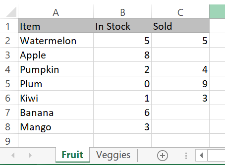
getLastCol() = 3
getLastCol("Fruit") = 3
getLastCol(,3) = 2 'last used column on row 3 only
getLastCol(Vegetables) = 0 'this sheet name does not exist
The Code:
Function getLastCol(Optional sheetName As String, Optional rowNum As Long, Optional colLimit As Long) As Long
'by Elliot 7/22/20 www.elliotmade.com
'this function will return the last used column on a sheet in a single row
'if no sheet name is specified it will use the active sheet
'if no row is specified it will find the last column in any row up to an optional limit (for faster performance)
'two assumptions are made: the file type is .xlsx or similar that supports 16k columns
'and the sheet is in the active workbook
'a zero returned means that there was a failure

Dim i As Long
Dim j As Long
Dim curLastCol As Long

'check for valid inputs first, return zero if there is a problem
If rowNum < 0 Or rowNum > 1048575 Then GoTo abort

If sheetName <> "" Then
    For i = 1 To Worksheets.Count
        If Worksheets(i).Name = sheetName Then GoTo sheetOK
    Next i
    GoTo abort 'specified sheet name was not found
sheetOK:
End If

If colLimit = 0 Then
    colLimit = 16384
ElseIf colLimit < 0 Or colLimit > 16384 Then
    GoTo abort
End If

If sheetName = "" Then sheetName = ActiveSheet.Name

'if no problem, find the last column
If rowNum = 0 Then
    getLastCol = Worksheets(sheetName).Cells(1, 16384).End(xlToLeft).Column
    For j = 1 To colLimit
        If Worksheets(sheetName).Cells(1048575, j).End(xlUp).Row > 1 Then curLastCol = j
        If curLastCol > getLastCol Then getLastCol = curLastCol
    Next j
Else
    getLastCol = Worksheets(sheetName).Cells(rowNum, 16384).End(xlToLeft).Column
End If

abort:

End Function
You may notice that the method using xlToLeft is used to find the last column in a specific row, but I did not use it when searching for the last column in the entire sheet; to do this in a loop would require iterating through every single row (over 1M!) and would take a significant amount of time. I chose to do two things to shortcut this process: first, check the first row because it often has headings for the rest of the document, and second, find the last used row in every column instead. This limits the possible trips through the loop to 16k at most (the number of columns in a sheet). I have some other ideas to improve on this, but I’ll leave it alone for now until it becomes a bottleneck.
Next I’ll post an example that puts this function to use, stay tuned.
If you’re getting into Excel macros and have fooled around with the macro recorder you may notice that the resulting code is very rigid: it only works on the exact range of cells you had selected for example (among other drawbacks). In many cases you want your code to adapt to the size of the data in a sheet, and for this you need to determine the boundaries of the range.
.UsedRange Property
If you’ve done a search you may have come across this approach already. .UsedRange.Rows.Count will usually give the right result if you’re looking for the last used row on a particular sheet, but not always. For whatever reason, this property is not always current – sometimes it is possible to clear the contents of a row without causing this to update, giving an incorrect result. Saving the document (and probably some other actions) will cause this to be updated, but I don’t consider it to be reliable enough to base further logic on.
.End(xlUp).row
This approach is the equivalent of putting your cursor in a cell and pushing CTRL+UP. If you do this on the very last row of a sheet, the cell that your cursor lands on will be the last one in that column. This works reliably, but only gives a result for one column, not the entire sheet. If you put this together with a loop and repeat it for all columns (or a reasonable number) you can reliably retrieve the last used row on a sheet.
The function: getLastRow()
Putting this all together, an easy to use function can be made that returns the last row number on a sheet or in a specific column.
If called with no parameters it will return the last used row in the first 100 columns of the active sheet.
The optional sheetName parameter is useful to reference a sheet other than the active one, or if you can’t guarantee which sheet is active when the function is called.
The second optional parameter, colNum, can be used if you want to know the last used row in a specific column.
Examples
Here are some examples of how this works with the sample sheet below:
getLastRow() = 8 'from the active sheet
getLastRow("Fruit") = 8 'even when a different sheet is active
getLastRow(,3) = 6 'from the active sheet
getLastRow("Fruit", 3) = 6 'even when a different sheet is active
getLastRow("Fruit", 4) = 1 'this column is empty
getLastROW("Vegetables") = 0 'this sheet name is invalid
And finally, the function itself:
Function getLastRow(Optional sheetName As String, Optional colNum As Long) As Long
'by Elliot 7/22/20 www.elliotmade.com
'this function will return the last used row on a sheet or a single row
'if no sheet name is specified it will use the active sheet
'if no column is specified it will find the last row in any of the first 100 columns
'two assumptions are made: the file type is .xlsx or similar that supports ~1M rows
'and the sheet is in the active workbook

'a zero returned means that there was a failure

Dim i As Long
Dim j As Long
Dim curLastRow As Long

'check for valid inputs first, return zero if there is a problem
If colNum < 0 Or colNum > 16384 Then GoTo abort

If sheetName <> "" Then
    For j = 1 To Worksheets.Count
        If Worksheets(j).Name = sheetName Then GoTo sheetOK
    Next j
    GoTo abort 'specified sheet name was not found
sheetOK:
End If

If sheetName = "" Then sheetName = ActiveSheet.Name

'if no problem, find the last row
If colNum = 0 Then
For i = 1 To 100
    curLastRow = Worksheets(sheetName).Cells(1048575, i).End(xlUp).Row
    If curLastRow > getLastRow Then getLastRow = curLastRow
Next i

Else
    curLastRow = Worksheets(sheetName).Cells(1048575, colNum).End(xlUp).Row
End If

abort:

getLastRow = curLastRow

End Function
If you found this useful, or if you have a problem this might help you solve, let me know!
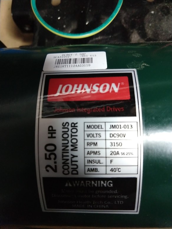
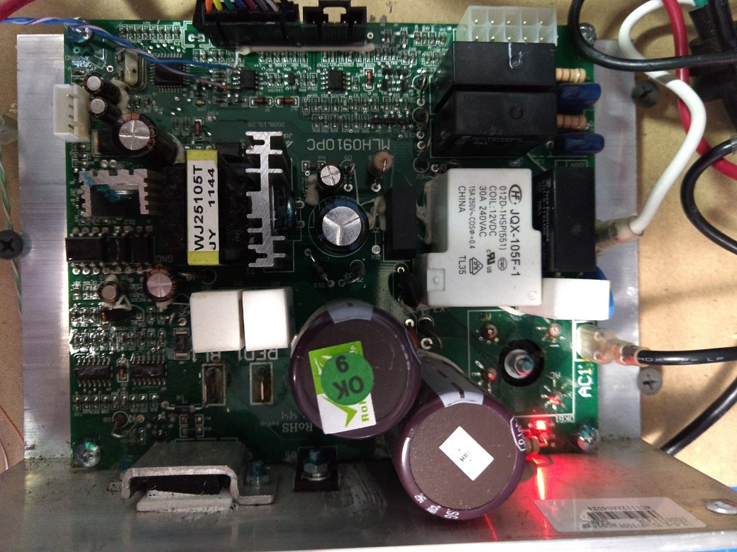
I scrapped a treadmill and salvaged the motor for a belt grinder project. My goal is to chuck the original control panel and just use the motor and it’s controller… but unlike the previous treadmill I did this to, interfacing with this one was not as simple as feeding it a PWM signal. The motor is a Johnson 90v DC motor, model JM01-013, and the control board is labeled MLH0910PC. I’m hoping the following information helps at least one other person – I spent hours searching and wasn’t able to come up with anything useful.
The control panel (I’ll refer to this as the panel going forward) has all of the displays and connects to the rest of the interface buttons and the safety key switch. The motor controller contains the AC connection, runs the motor and incline, as well as supplies power for the panel.
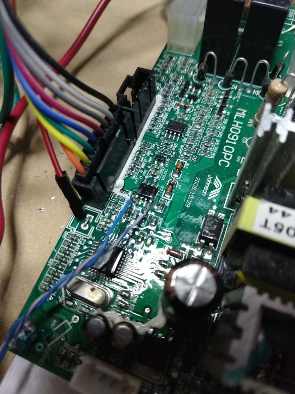
There is a single cable connecting the controller and panel with 8 wires: two are the safety key switch and pass straight through to the controller, two for power, two for ground, and the last two are for serial data. On both ends of the connector there is a MAX3085 RS-485 transceiver chip. Initially I used a MAX485 on a breakout board to listen in, but I was struggling to extract useful data with a logic analyzer and PulseView. It was clear that there was a message and response from one unit to the other, but for whatever reason I wasn’t able to reliably pick up the start and end bits for the response. I had much better luck connecting the logic analyzer directly to pins 1 and 4 of the MAX3085 (on either board works)… this let me see the RX and TX data on separate channels, then it could be decoded easily.
Logic analyzer connected to pins 1 and 4
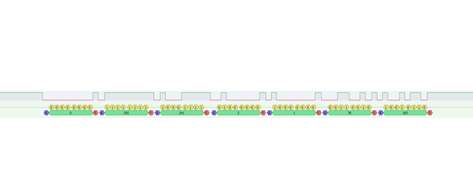
From what I can tell the panel is the master, it always initiates communication (either a command or a query), and the controller only responds. Messages are sent roughly every 70-100 ms at 9600 baud and consist of 5-7 bytes. The first two bytes look like an identifier: the panel prefix is 0-255, and the controller is 0-127. I looked at all of this in decimal because why not, also it made it easy to work with in Excel. I was able to isolate the packet from the panel that seemed to control the speed, then I recorded the values for every speed available from .5 to 12 MPH in tenth of a MPH increments.
I used an arduino to replay all of the messages through the MAX485 from power-up to running and was pleased to see the motor start to run (I kept the safety switch shorted). Working backwards, I started eliminating the different messages until all I had left was the speed command and the motor continued to run – showing me that I can ignore pretty much everything else – great! Did some more experimentation and here is what I found:
Only speed commands are needed
All acknowledgements from the controller can be ignored
Any new speed lower than the current one will be accepted by the controller and it will coast down to that setting
A new speed higher than the current one will be accepted if it is not too much higher. For example, the motor will accelerate from 5 to 5.1 mph
A new speed too much higher than the current one will be rejected and the motor will coast to a stop. For example, commanding it to accelerate from 5 to 12 mph.
Speed changes are very gradual (probably to keep you from falling on your face and/or butt)
It won’t exceed 4000 RPM (12 mph), or perhaps I picked bogus values when I tried
This means that interfacing with this is going to be pretty easy. My approach was just to create a lookup table for the known speeds that I mapped out. When increasing the speed I ramp through each of the steps on the way to the final target speed, this seems to keep the controller happy and it doesn’t panic and coast to a stop. There is no need to ramp down to a slower speed, only to a higher one.
Example packet
The 7-byte packet that controls speed is pictured above. I mapped all of the speeds from zero to twelve MPH, see the table below. RPM was measured with no load, but I expect it to be similar under load – the motor has a toothed wheel (maybe optical or probably hall-effect) and I’m guessing it uses closed-loop speed control.
Mission accomplished! I’ve actually had this motor sitting around for over a year but never made any headway on figuring out how to control it, now I can move on and make something useful with it.
MPH
Byte 1
Byte 2
Byte 3
Byte 4
Byte 5
Byte 6
Byte 7
Measured RPM
0.0
0
255
241
2
0
0
221
0
0.5
0
255
241
2
0
161
16
0.6
0
255
241
2
0
195
201
0.7
0
255
241
2
0
230
186
0.8
0
255
241
2
1
8
144
0.9
0
255
241
2
1
42
116
1.0
0
255
241
2
1
76
105
332
1.1
0
255
241
2
1
111
188
1.2
0
255
241
2
1
145
33
1.3
0
255
241
2
1
179
197
1.4
0
255
241
2
1
213
216
1.5
0
255
241
2
1
248
18
1.6
0
255
241
2
2
26
156
1.7
0
255
241
2
2
60
188
1.8
0
255
241
2
2
94
101
1.9
0
255
241
2
2
129
79
2.0
0
255
241
2
2
163
171
670
2.1
0
255
241
2
2
197
182
2.2
0
255
241
2
2
231
82
2.3
0
255
241
2
3
10
43
2.4
0
255
241
2
3
44
11
2.5
0
255
241
2
3
78
210
2.6
0
255
241
2
3
112
8
2.7
0
255
241
2
3
147
154
2.8
0
255
241
2
3
181
186
2.9
0
255
241
2
3
215
99
3.0
0
255
241
2
3
249
250
1016
3.1
0
255
241
2
4
28
96
3.2
0
255
241
2
4
62
132
3.3
0
255
241
2
4
96
229
3.4
0
255
241
2
4
130
70
3.5
0
255
241
2
4
165
87
3.6
0
255
241
2
4
199
142
3.7
0
255
241
2
4
233
23
3.8
0
255
241
2
5
11
64
3.9
0
255
241
2
5
46
51
4.0
0
255
241
2
5
80
212
1358
4.1
0
255
241
2
5
114
48
4.2
0
255
241
2
5
148
87
4.3
0
255
241
2
5
183
130
4.4
0
255
241
2
5
217
38
4.5
0
255
241
2
5
251
194
4.6
0
255
241
2
6
29
136
4.7
0
255
241
2
6
64
186
4.8
0
255
241
2
6
98
94
4.9
0
255
241
2
6
132
57
5.0
0
255
241
2
6
166
221
1700
5.1
0
255
241
2
6
200
121
5.2
0
255
241
2
6
235
172
5.3
0
255
241
2
7
13
63
5.4
0
255
241
2
7
47
219
5.5
0
255
241
2
7
81
60
5.6
0
255
241
2
7
116
79
5.7
0
255
241
2
7
150
236
5.8
0
255
241
2
7
184
117
5.9
0
255
241
2
7
218
172
6.0
0
255
241
2
7
253
189
2042
6.1
0
255
241
2
8
31
135
6.2
0
255
241
2
8
65
230
6.3
0
255
241
2
8
99
2
6.4
0
255
241
2
8
134
54
6.5
0
255
241
2
8
164
175
6.6
0
255
241
2
8
202
118
6.7
0
255
241
2
8
236
86
6.8
0
255
241
2
9
15
112
6.9
0
255
241
2
9
49
234
7.0
0
255
241
2
9
83
51
2385
7.1
0
255
241
2
9
117
19
7.2
0
255
241
2
9
152
158
7.3
0
255
241
2
9
186
122
7.4
0
255
241
2
9
220
103
7.5
0
255
241
2
9
254
131
7.6
0
255
241
2
10
33
132
7.7
0
255
241
2
10
67
93
7.8
0
255
241
2
10
101
125
7.9
0
255
241
2
10
135
222
8.0
0
255
241
2
10
170
20
2725
8.1
0
255
241
2
10
204
9
8.2
0
255
241
2
10
238
237
8.3
0
255
241
2
11
16
132
8.4
0
255
241
2
11
51
81
8.5
0
255
241
2
11
85
76
8.6
0
255
241
2
11
119
168
8.7
0
255
241
2
11
153
118
8.8
0
255
241
2
11
188
5
8.9
0
255
241
2
11
222
220
9.0
0
255
241
2
12
0
105
3070
9.1
0
255
241
2
12
34
141
9.2
0
255
241
2
12
101
161
9.3
0
255
241
2
12
103
69
9.4
0
255
241
2
12
137
139
9.5
0
255
241
2
12
171
127
9.6
0
255
241
2
12
206
49
9.7
0
255
241
2
12
240
235
9.8
0
255
241
2
13
18
188
9.9
0
255
241
2
13
52
156
10.0
0
255
241
2
13
87
116
3414
10.1
0
255
241
2
13
121
237
10.2
0
255
241
2
13
155
78
10.3
0
255
241
2
13
173
110
10.4
0
255
241
2
13
224
92
10.5
0
255
241
2
14
2
210
10.6
0
255
241
2
14
36
242
10.7
0
255
241
2
14
70
43
10.8
0
255
241
2
14
105
131
10.9
0
255
241
2
14
139
32
11.0
0
255
241
2
14
173
0
3752
11.1
0
255
241
2
14
207
217
11.2
0
255
241
2
14
242
80
11.3
0
255
241
2
15
20
195
11.4
0
255
241
2
15
54
39
11.5
0
255
241
2
15
88
131
11.6
0
255
241
2
15
123
86
11.7
0
255
241
2
15
157
49
11.8
0
255
241
2
15
191
213
11.9
0
255
241
2
15
225
180
12.0
0
255
241
2
16
4
119
3996
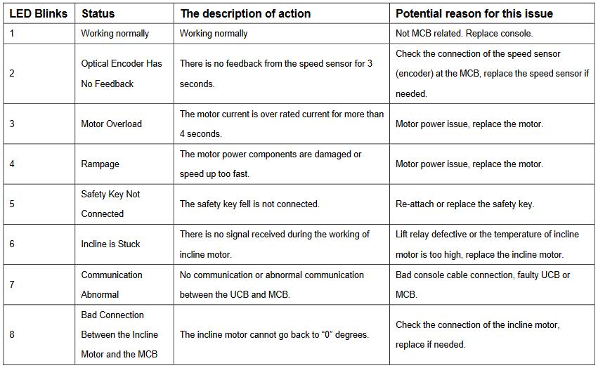
Edit 10/25/21: Here are the codes blinked out by the control board:
And here is a simple arduino sketch. You can probably ignore the 7-segment and rotary encoder parts, but it is successfully controlling the motor drive through a MAX485 chip on a breakout board.
/*
 * Encoder on A2, A3
 * Button on A1
 * MAX 485: 5v to DE, D8 to DI.  A and B to A and B of the treadmill controller
 * TM1637 display clock on 2, data on 3
 * Short out the middle "safety key" pins
 * Take power from one of the treadmill controller pins (which one?)
 * Treadmill header has 8 pins (left to right, latch at the bottom):
 * 1 - 12v
 * 2 - 12v
 * 3 - A or B?
 * 4 - Safety switch
 * 5 - Safety switch
 * 6 - A or B?
 * 7 - Ground
 * 8 - Ground
*/


#include <AltSoftSerial.h>
//https://www.pjrc.com/teensy/td_libs_AltSoftSerial.html

#include <SimpleTimer.h>
//https://github.com/jfturcot/SimpleTimer

#include <RotaryEncoder.h>
//http://www.mathertel.de/Arduino/RotaryEncoderLibrary.aspx
//https://github.com/mathertel/RotaryEncoder

#include "OneButton.h"
//https://github.com/mathertel/OneButton

#include <TM1637Display.h>
//https://github.com/avishorp/TM1637

#include <EEPROMex.h>
//https://github.com/thijse/Arduino-EEPROMEx

const int encoderButton = A1;
const int encoderA = A2;
const int encoderB = A3;
const int dispClock = 2; //D2
const int dispData = 3; //D3


AltSoftSerial ss;
SimpleTimer timer;
OneButton encoderButt(encoderButton, true);
RotaryEncoder encoder(A2, A3);
TM1637Display display1(dispClock, dispData);

bool halt = true;
int setSpeed = 0;
int curSpeed = 0; //ramp this up until it reaches the set speed
int savedSpeed = 0;
const int speedCount = 123;

const byte b1[] = {0,0,0,0,1,1,1,1,1,1,1,1,2,2,2,2,2,2,2,3,3,3,3,3,3,3,3,4,4,4,4,4,4,4,5,5,5,5,5,5,5,5,6,6,6,6,6,6,6,7,7,7,7,7,7,7,7,8,8,8,8,8,8,8,9,9,9,9,9,9,9,9,10,10,10,10,10,10,10,11,11,11,11,11,11,11,12,12,12,12,12,12,12,12,13,13,13,13,13,13,13,14,14,14,14,14,14,14,14,15,15,15,15,15,15,15,16,16,16,16,16,16,16,16};
const byte b2[] = {0,161,195,230,8,42,76,111,145,179,213,248,26,60,94,129,163,197,231,10,44,78,112,147,181,215,249,28,62,96,130,165,199,233,11,46,80,114,148,183,217,251,29,64,98,132,166,200,235,13,47,81,116,150,184,218,253,31,65,99,134,164,202,236,15,49,83,117,152,186,220,254,33,67,101,135,170,204,238,16,51,85,119,153,188,222,0,34,101,103,137,171,206,240,18,52,87,121,155,173,224,2,36,70,105,139,173,207,242,20,54,88,123,157,191,225,4,20,54,88,123,157,191,225};
const byte b3[] = {221,16,201,186,144,116,105,188,33,197,216,18,156,188,101,79,171,182,82,43,11,210,8,154,186,99,250,96,132,229,70,87,142,23,64,51,212,48,87,130,38,194,136,186,94,57,221,121,172,63,219,60,79,236,117,172,189,135,230,2,54,175,118,86,112,234,51,19,158,122,103,131,132,93,125,222,20,9,237,132,81,76,168,118,5,220,105,141,161,69,139,127,49,235,188,156,116,237,78,110,92,210,242,43,131,32,0,217,80,195,39,131,86,49,213,180,119,195,39,131,86,49,213,180};
const int sfm[] = {0,262,314,366,418,471,523,575,628,680,732,785,837,889,941,994,1046,1098,1151,1203,1255,1308,1360,1412,1464,1517,1569,1621,1674,1726,1778,1831,1883,1935,1987,2040,2092,2144,2197,2249,2301,2355,2406,2458,2510,2563,2615,2667,2721,2772,2824,2878,2929,2981,3033,3087,3138,3190,3244,3295,3347,3401,3453,3504,3556,3610,3661,3713,3767,3818,3870,3924,3976,4027,4079,4133,4184,4236,4290,4342,4393,4447,4499,4550,4602,4656,4708,4759,4813,4865,4916,4970,5022,5074,5125,5179,5231,5282,5336,5388,5440,5493,5545,5597,5648,5702,5754,5805,5859,5911,5963,6016,6068,6120,6171,6225,6277,6329,6382,6434,6486,6539,6591,6643};

//eeprom memory locations
const int memAddress = 20;
const int memBase = 350;


void setup() {
  //interrupts for encoder
  PCICR |= (1 << PCIE1);    // This enables Pin Change Interrupt 1 that covers the Analog input pins or Port C.
  PCMSK1 |= (1 << PCINT10) | (1 << PCINT11);  // This enables the interrupt for pin 2 and 3 of Port C.
  //Serial.begin(9600);
  ss.begin(9600);
  timer.setInterval(100, sendSpeedPacket);
  encoderButt.attachClick(startStop);

  // Set Up EEPROM
  EEPROM.setMemPool(memBase, EEPROMSizeNano);

  //Load the stored speed value
  setSpeed = EEPROM.readInt(memAddress);

  display1.setBrightness(2);
  updateDisplay();
}

void loop() {
  // put your main code here, to run repeatedly:
  timer.run();
  encoderButt.tick();
  readEncoder();
  updateDisplay();
}

void sendSpeedPacket() {

  if(halt == true) { //send the stop packet
    ss.write((byte)0);
    ss.write((byte)255);
    ss.write((byte)241);
    ss.write((byte)2);
    ss.write((byte)0);
    ss.write((byte)0);
    ss.write((byte)221);
  }
  else { //send the current speed packet
    ss.write((byte)0);
    ss.write((byte)255);
    ss.write((byte)241);
    ss.write((byte)2);
    ss.write((byte)b1[curSpeed]);
    ss.write((byte)b2[curSpeed]);
    ss.write((byte)b3[curSpeed]);
  }

  if (halt == true){
    curSpeed = 0;
  }

  if (curSpeed < setSpeed && halt == false) { //this ramps the sent speed up until it hits the set speed
    curSpeed++;
  }
  if (curSpeed > setSpeed && halt == false) { //this immediately reduces the sent speed to the set speed
    curSpeed = setSpeed;
  }

  //Serial.print(halt);
  //Serial.print(" ");
  //Serial.println(curSpeed);

}

void startStop () {
  halt = !halt;
  EEPROM.writeInt(memAddress, setSpeed); //save the speed every time the button is pushed... so that on next power up it is not zero
}

void readEncoder() {
  static int pos = 0;

  int newPos = encoder.getPosition();
      if (pos > newPos) {
        setSpeed = setSpeed - 1;
      }
      else if (pos < newPos) {
        setSpeed = setSpeed + 1;
      }
      pos = newPos; //--keep

      setSpeed = constrain(setSpeed, 0, speedCount);


}

ISR(PCINT1_vect) {
  encoder.tick(); // just call tick() to check the state.
}


void updateDisplay() {
  display1.showNumberDecEx(sfm[setSpeed], 0, true);  //Set time should always show on display 1
//  Serial.print("Minutes: ");
//  Serial.print(seconds / 60);
//  Serial.print("Seconds: ");
//  Serial.println(seconds & 60);
}
Update 11/2022 – here’s a list of some of the unique commands I saw. I didn’t test or try to capture the incline setting, but if we’re lucky maybe it’s in here:
These are the unique commands and responses I recorded just after powering up:
Source	Unique Message		Count	Comment
Panel	0 255 14 0 14			1
Motor	128 0 14 0 5			1
Panel	0 255 9 64 0 95 241		2
Motor	128 0 9 0 107			2
Panel	0 255 159 0 9			30	Common while idle and running
Motor	128 0 159 64 0 0 160	30	Probably reply to 0 255 159 09
Panel	0 255 143 64 0 0 187	81	Speed command? 143
Motor	128 0 143 0 238			81


And here are the unique commands while it was running at a steady .5 mph:
Source	Message						Count	Comment
Panel	0 255 143 64 0 133 8		77	Speed command? 143
Motor	128 48 143 0 48				77	Same acknowledgement to speed command as 1 mph
Panel	0 255 111 64 0 20 14		76	Same while running at 1 mph
Motor	128 48 111 0 69				76	same response as running at 1 mph
Panel	0 255 159 0 9				23	Common while idle or running
Motor	128 48 159 64 0 37 56		11
Motor	128 48 159 64 0 165 180		10
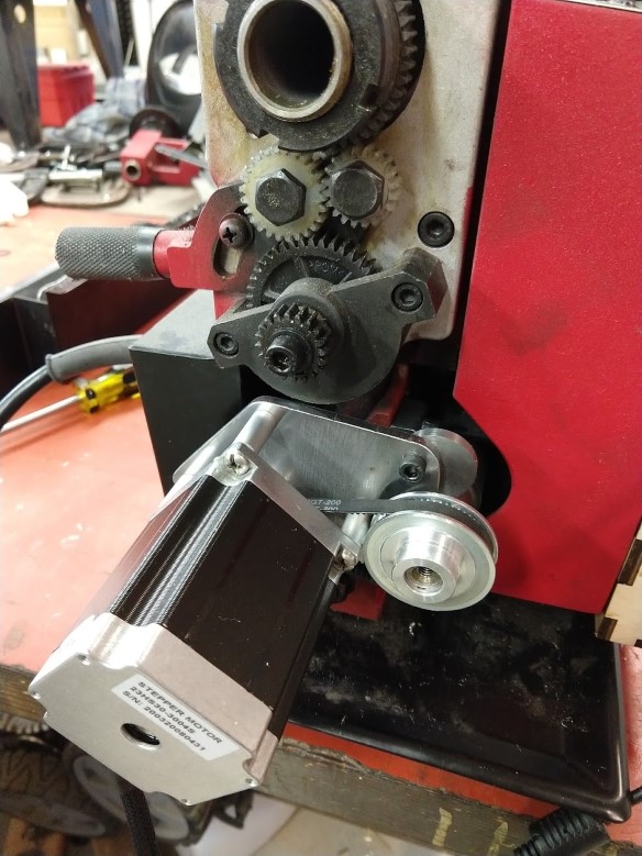
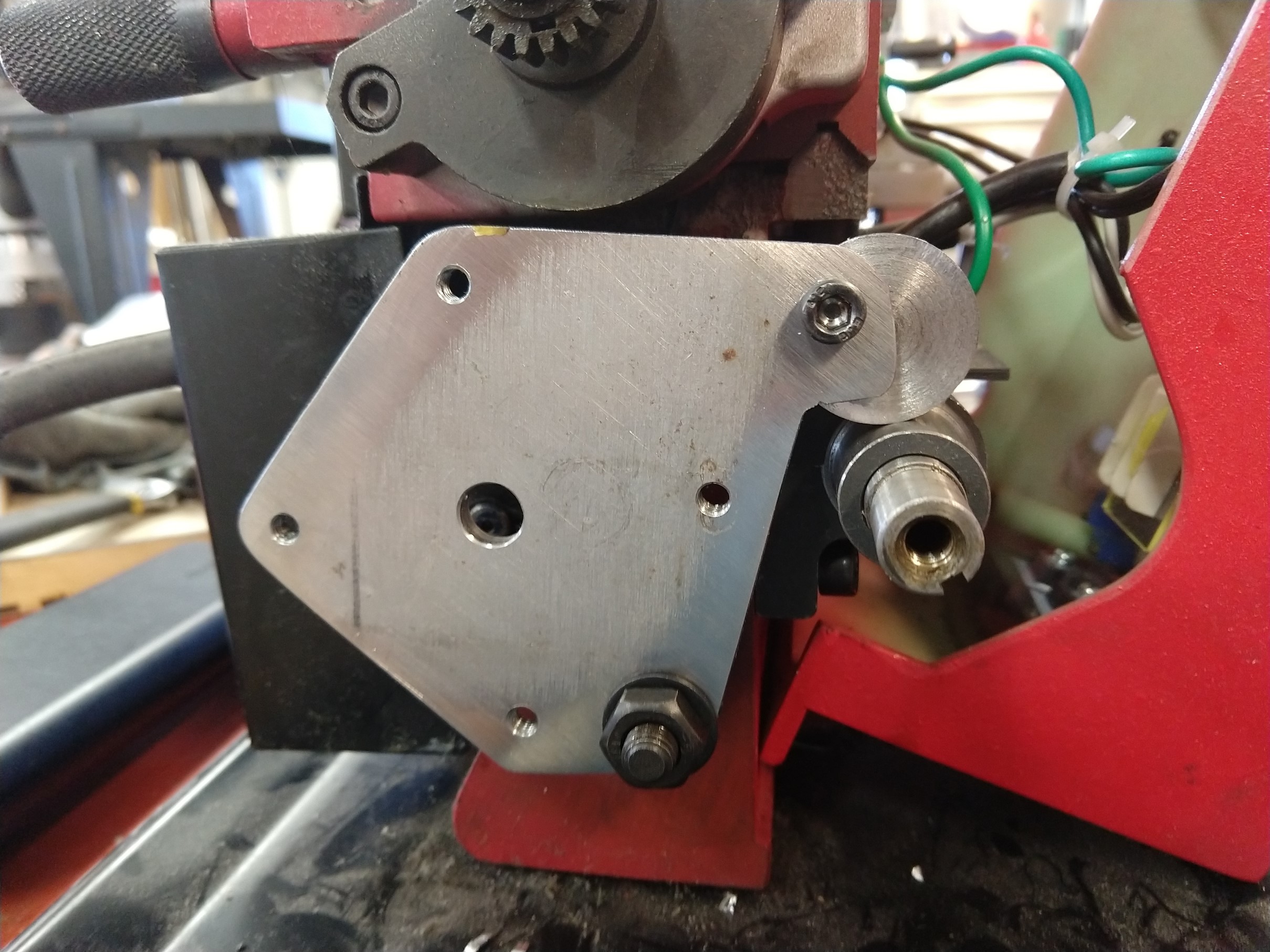
This mount puts the motor on the left side of the lathe and replaces the original banjo for the changegears. This is the easiest/cheapest way I could come up with to attach the motor to the leadscrew. Originally I intended to extend the leadscrew and drive it from the tail end, but that is a bit more challenging and I thought this would be easier for the home-shop. The motor will interfere with the cover, so you may need to cut a hole in it or leave it off. I put some thought into this so that it could be made with basic tools (no slots, welding, etc).
Bill of Materials
Quantity
Description
1
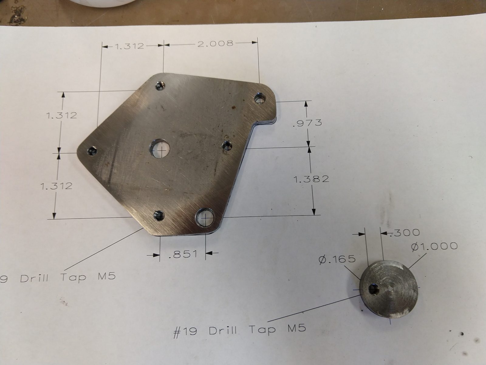
Steel or aluminum plate 4″ x 5″ (or larger). 3/16″ or 1/4″ thick
4
M5 x .8 Screw – 35mm long
1
M5 x .8 Screw – 15mm long
4
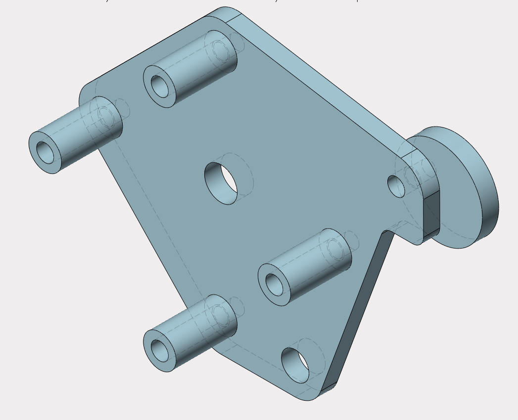
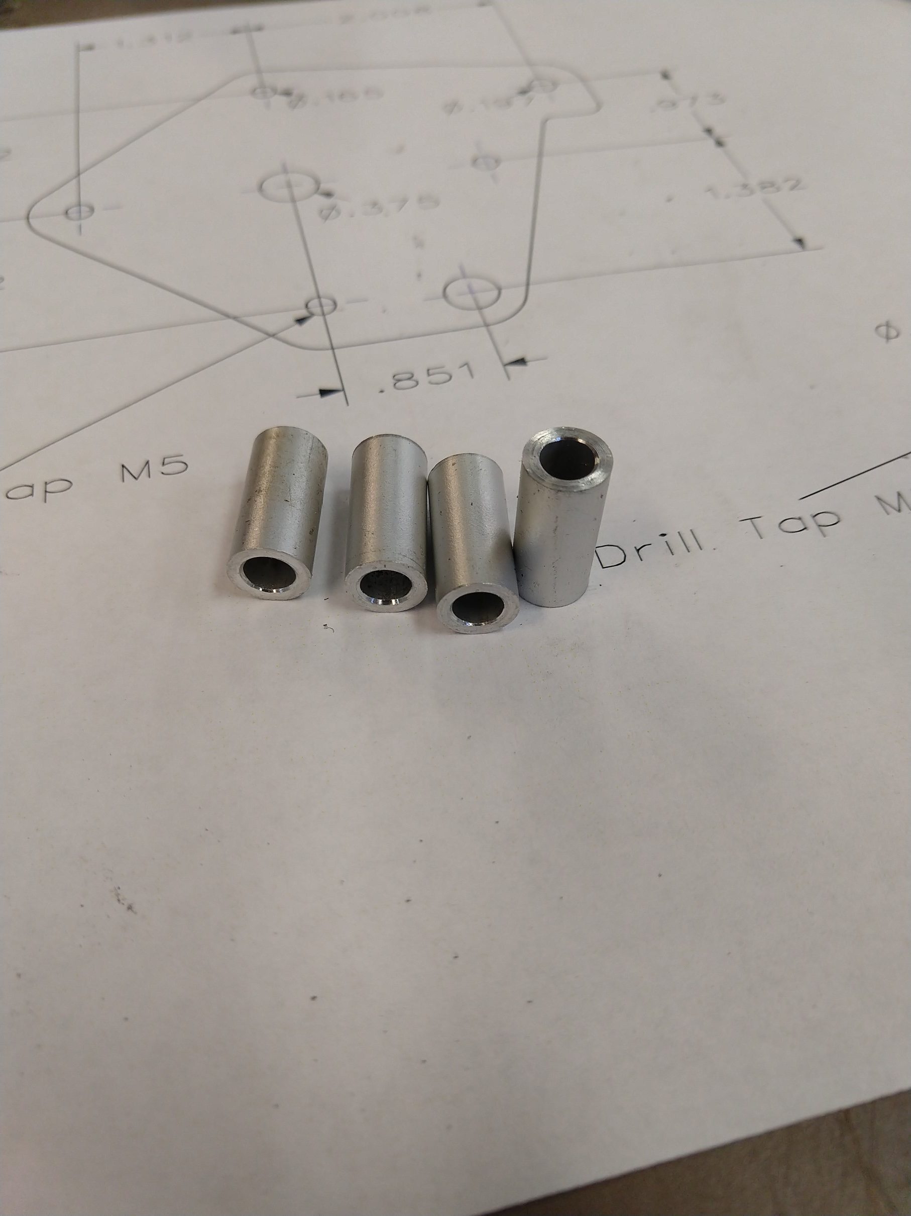
Spacer 5mm ID – .700″ long (see drawing) (make from round stock)
1
NEMA 23 Stepper (notes below)
1
GT2 pulley – 60 tooth 12mm bore
1
GT2 pulley – 20 tooth (bore to match stepper shaft)
1
GT2 belt – 200 tooth, 6mm wide
Tools required
M5 x .8 tap
4.2mm or #19 drill for M5
8mm or O drill (.3160″)
5mm or #7 or #8 drill
Tools for cutting the plate
Hacksaw and a drill is the basic requirement
Bandsaw, scroll saw, mill, CNC, LASER… these are optional. Use whatever you want
File or sandpaper
Lathe (for making spacers)
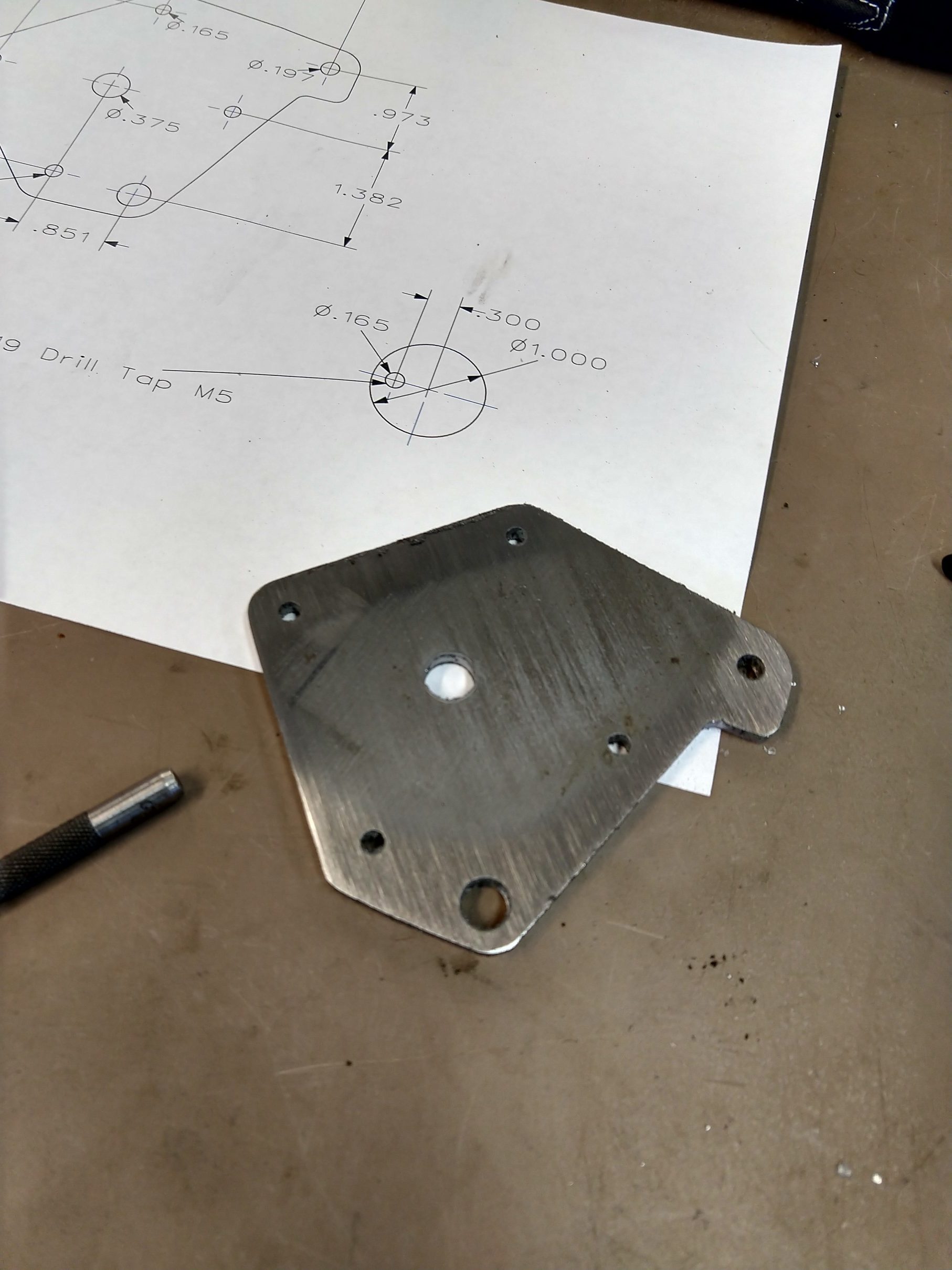
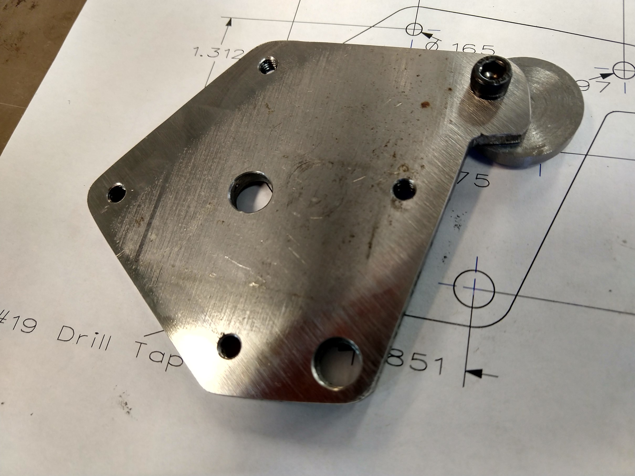
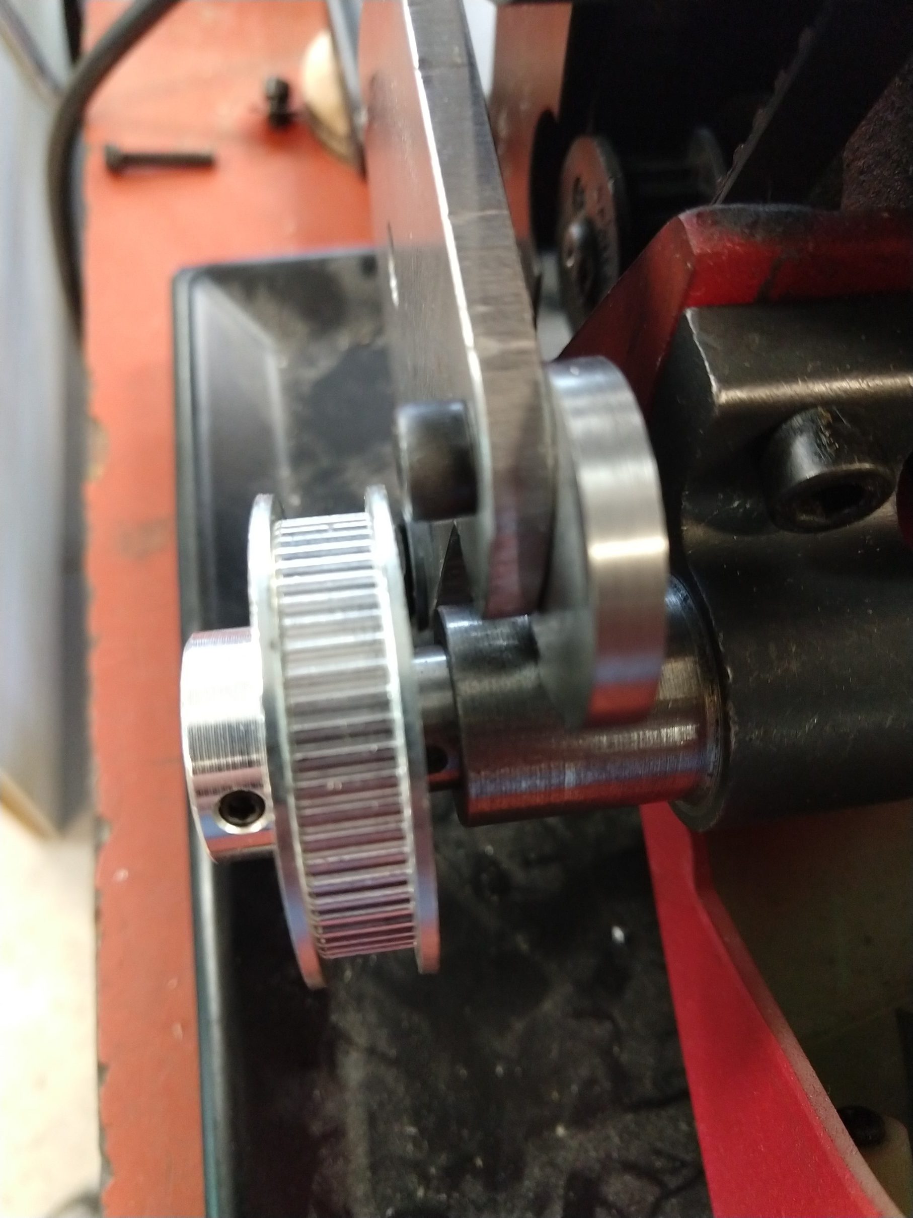
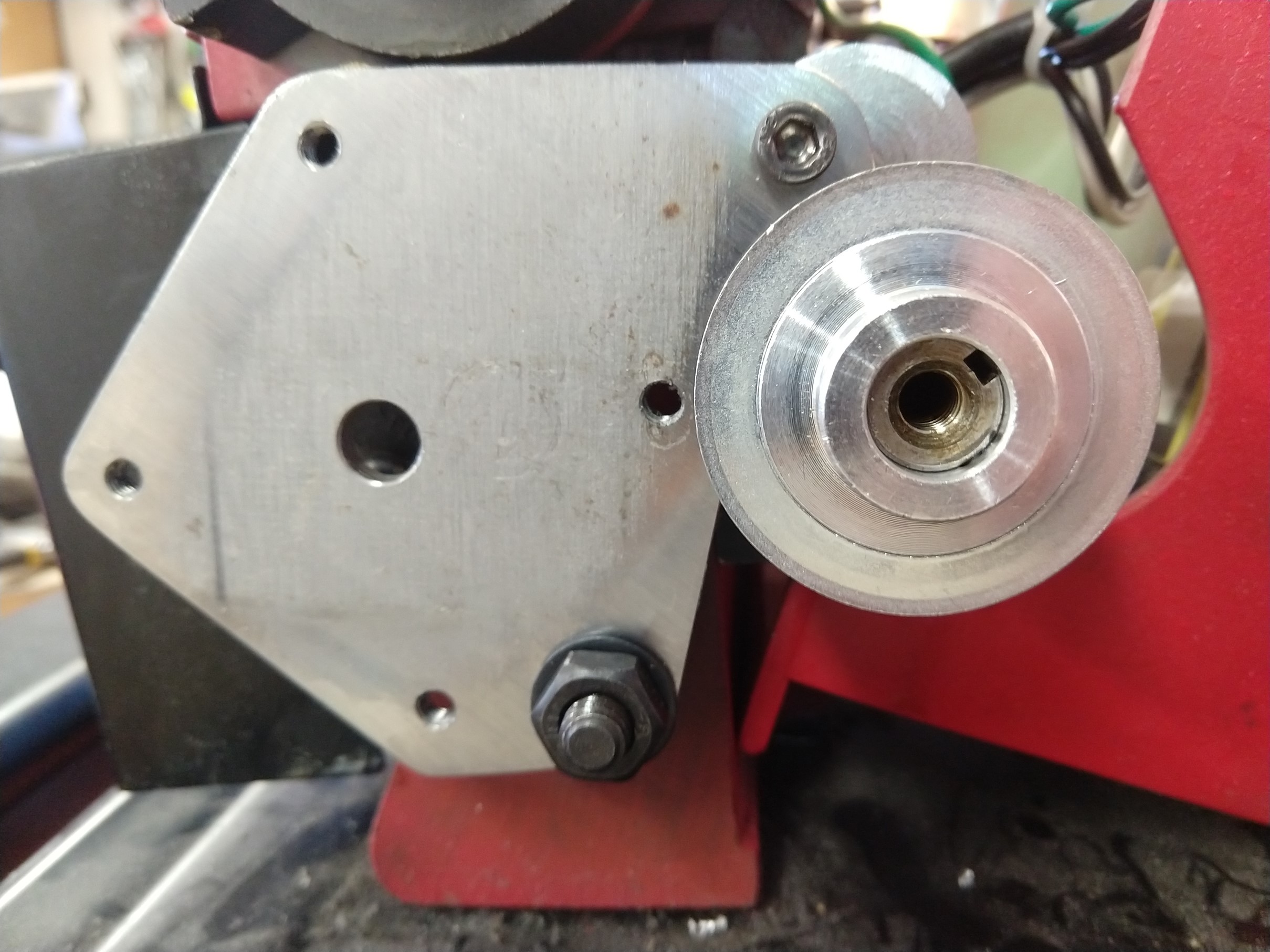
The only critical dimensions on this part are the four tapped M5 holes for mounting the motor. It is also important that the four spacers be the same length so the motor is square to the plate. Other than that, the outside contour of the part only needs to clear any obstructions. The circular part with the offset hole is used to adjust the belt tension, it rotates and presses against the leadscrew bushing/bearing – if that doesn’t make sense it should be more clear in the photo. The OD of the spacers is only important for the one that is closest to the leadscrew pulley, it may be necessary to relieve this for clearance.
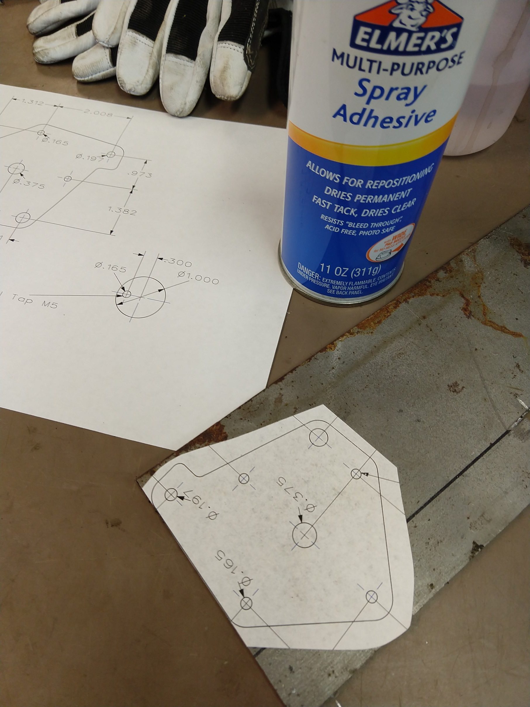
I recommend printing the drawing out at 1:1 scale and gluing it to your plate, center punch the hole locations for drilling and use a saw and files to get the right outside shape.
Hopefully it is clear how this mounts up to the lathe in the photos. Take off all of the change gears including the key on the leadscrew and set them aside (or probably lose them forever, which is what I will probably do). The banjo also needs to be removed, but the nut and washer will be reused. Don’t tighten the set screws on the pulleys until you have the motor mounted, this way you can shift them around for alignment. Remember to put the belt on!
Use drawing as a template
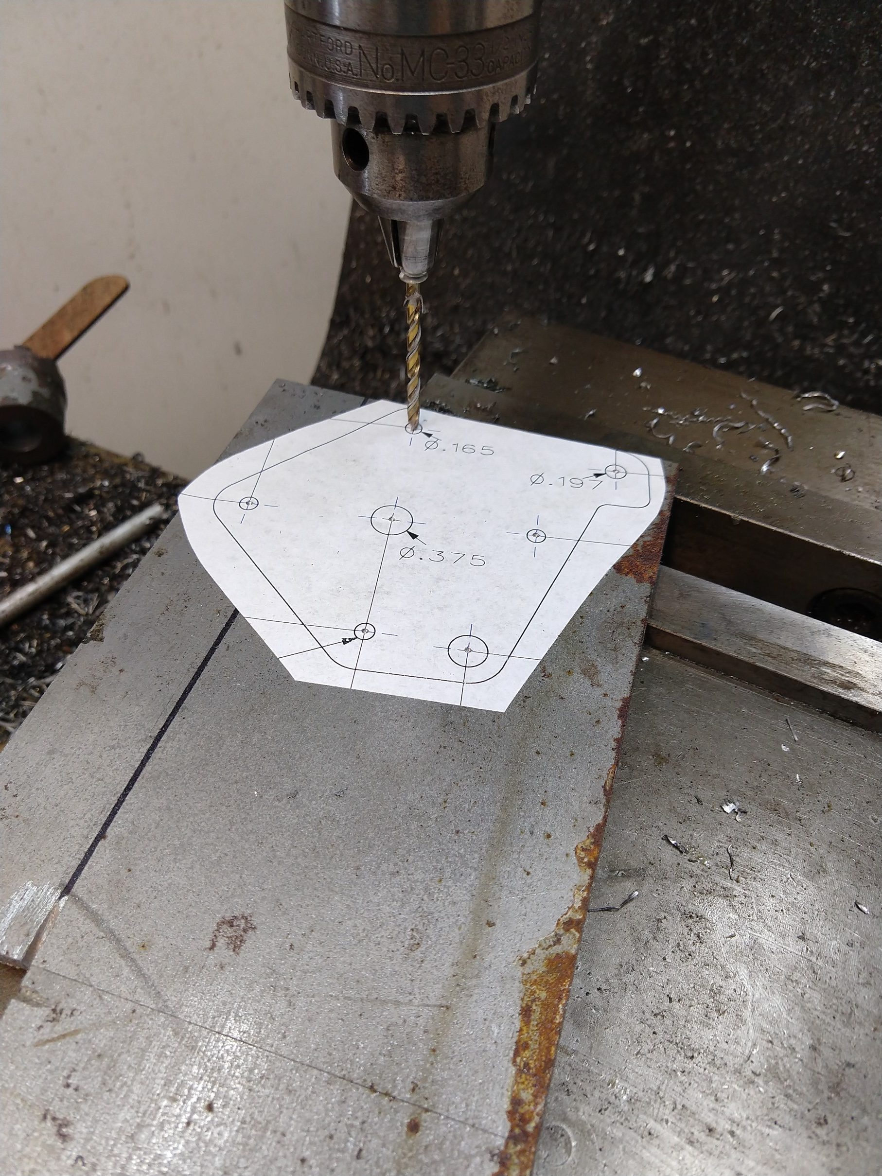
Center punch and drill
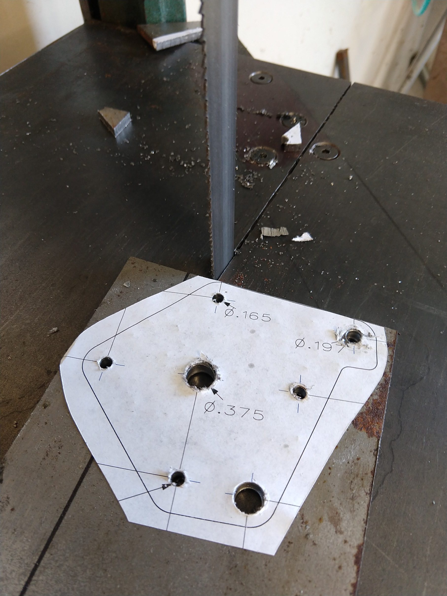
Cut outline
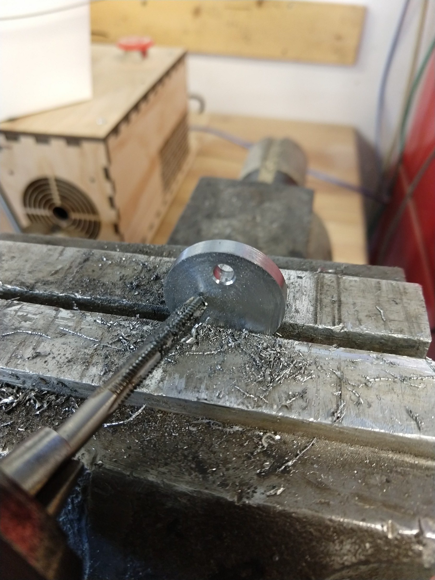
Tap 5mm holes
Assembled
Replaces the banjo
Spacers
Regarding the motor – I chose a 1.9 nm stepper. I have not tested this thoroughly yet, but so far I have this running at 2 amps and it doesn’t seem to have any trouble moving the carriage while cutting in aluminum. I think a smaller motor will probably be sufficient – but I don’t know the limits yet.
That’s it! I’ll follow up with the details for the control in another post.
Rainy day today, got the prototype firmware working. For whatever reason using a display and sending pulses to a stepper motor with the Uno was a real struggle. I tried several different libraries for the I2C LCD and stepper motor and wasn’t able to get a single update done quickly enough to fit between steps. This was easy to hear, sometimes you can see it, and depending on the pulse frequency it would even stall the stepper or cause it to reverse direction if it was changing speed at the same time. At this point I am just not updating the display in the “Jog” mode until you stop or change direction – the numbers are really meaningless anyways and if you’re cutting you should adjust it by looking at the tool not the screen. My 3D printer can do it without a problem, wonder how?